Indium seal method for tight connection between laser crystal and red copper heat sink

A technology of laser crystal and red copper, which is applied to lasers, laser parts, phonon exciters, etc., can solve the problems of large thermal resistance and difficulty in achieving efficient heat dissipation, and achieve the effects of increasing contact area, soft texture, and improving heat dissipation efficiency

Inactive Publication Date: 2015-07-08
HARBIN INST OF TECH
View PDF4 Cites 4 Cited by
  • Summary
  • Abstract
  • Description
  • Claims
  • Application Information

AI Technical Summary

Problems solved by technology

However, the indium foil wrapping method is difficult to fill the small gap between the copper heat sink and the laser crystal to

Method used


Image

  • Indium seal method for tight connection between laser crystal and red copper heat sink

Examples


Example Embodiment

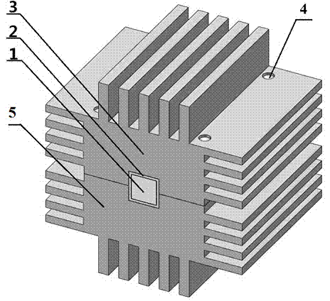
[0016] Specific implementation mode one: as figure 1 As shown, this embodiment provides a laser crystal heat sink based on the indium sealing welding process. The heat sink is mainly composed of a laser crystal 1, an indium foil 2, a copper heat sink and a screw 4 for fixing the copper heat sink.

[0017] In this embodiment, the copper heat sink is composed of an upper copper heat sink 3 and a lower copper heat sink 5, and the upper copper heat sink 3 has four through holes, and the lower copper heat sink 5 is provided with the upper copper heat sink 3. The positions of the upper through holes match the four threaded holes, and the upper copper heat sink 3 and the lower copper heat sink 5 are fastened and connected by four screws 4, and grooves are provided on the connection surface.

[0018] In this embodiment, the thickness of the indium foil is 0.5mm.

[0019] In this embodiment, the side of the laser crystal is wrapped with indium foil and put into the groove of the coppe...

Example Embodiment

[0023] Specific embodiment two: an indium sealing method for tightly connecting the laser crystal and the copper heat sink, which is realized by the following steps:

[0024] Step 1, cleaning off the oxide layer on the surface of the indium foil and the copper heat sink.

[0025] Step 2. Wrap the side of the laser crystal with indium foil and put it into the groove of the copper heat sink. The upper and lower copper heat sinks are fixed by screws.

[0026] Step 3. Put the connected and fixed red copper heat sink into the heating furnace, and the heating furnace is evacuated until the vacuum degree is about 0 torr.

[0027] Step 4: Heat the furnace to 160°C, and control the heating time for about 1 hour. Due to thermal inertia, the temperature will be about 170°C after 1 hour, and the indium foil will melt to weld the laser crystal and the copper heat sink.

[0028] Step 5. Turn off the heating furnace and take it out after the copper heat sink cools down.


PUM

PropertyMeasurementUnit
Thicknessaaaaaaaaaa

Abstract

The invention discloses an indium seal method for tight connection between a laser crystal and a red copper heat sink. The method comprises the steps that 1, oxidation layers on the surfaces of indium foil and the red copper heat sink are cleaned away; 2, the side face of the laser crystal is wrapped by the indium foil and then placed into a groove in the red copper heat sink; 3, the red copper heat sink is placed into a heating furnace, and the heating furnace is vacuumized; 4, the heating furnace is heated to be at the temperature ranging from 160 DEG C to 170 DEG C, the heating time is controlled to range from 1 h to 2 h, and the molten indium foil is used for welding the laser crystal to the red copper heat sink; 5, the heating furnace is closed, and the red copper heat sink is taken out after being cooled. According to the indium seal method, the laser crystal and the red copper heat sink are tightly connected in a seamless mode through the indium foil welding technology, the radiating efficiency of a whole laser radiating device is greatly improved, and the problem that the radiating efficiency is affected due to the fact that a traditional indium foil wrapping way is high in heat resistance is solved to a certain degree.

Description

technical field [0001] The invention relates to a laser crystal heat sink based on an indium sealing welding process and a method for realizing the tight connection between a laser crystal and a red copper heat sink by using the same. Background technique [0002] In LD-pumped solid-state lasers, the heat dissipation method for the end-pumped laser crystal is usually wrapped with indium foil and placed in a copper heat sink, and the waste heat in the laser crystal is transferred to the copper heat sink by heat conduction, and passed through It can be taken away by external water cooling or air cooling. However, the indium foil wrapping method is difficult to fill the small gap between the copper heat sink and the laser crystal to the maximum extent, resulting in large thermal resistance, which makes it difficult to achieve maximum efficient heat dissipation. Contents of the invention [0003] In order to realize the close connection between the laser crystal and the coppe...

Claims


Application Information

Patent Timeline
IPC IPC(8): H01S3/042
Inventor 李旭东闫仁鹏马欲飞樊荣伟董志伟法鑫于欣陈德应于俊华
Owner HARBIN INST OF TECH
Why Eureka
Try Eureka