Optical fiber coupling semiconductor laser device

A fiber coupling and semiconductor technology, applied in the laser field, can solve the problems of reducing the coupling efficiency of fiber-coupled semiconductor lasers and limiting the maximum optical power, etc., to achieve the effects of ensuring beam quality, increasing output power, and high transmittance

Inactive Publication Date: 2015-07-08
BWT BEIJING
View PDF7 Cites 8 Cited by
  • Summary
  • Abstract
  • Description
  • Claims
  • Application Information

AI Technical Summary

Problems solved by technology

[0011] For a given CoS, fiber and formula (4) limits the number of CoS that a fiber-coupled semiconductor laser can hold, which is equivalent to limiting the maximum optical power that a fiber-coupled semiconductor laser can output
[0012] At present, for fiber-coupled semiconductor lasers with CoS numbers between N and 2N, if all fiber-coupled semiconductor lasers adopt the form of polarization multiplexing, the coupling efficiency of fiber-coupled semiconductor lasers will inevitably be reduced; Beam quality is poorer than when using polarization multiplexing

Method used


Image

  • Optical fiber coupling semiconductor laser device
  • Optical fiber coupling semiconductor laser device
  • Optical fiber coupling semiconductor laser device

Examples


Embodiment 1

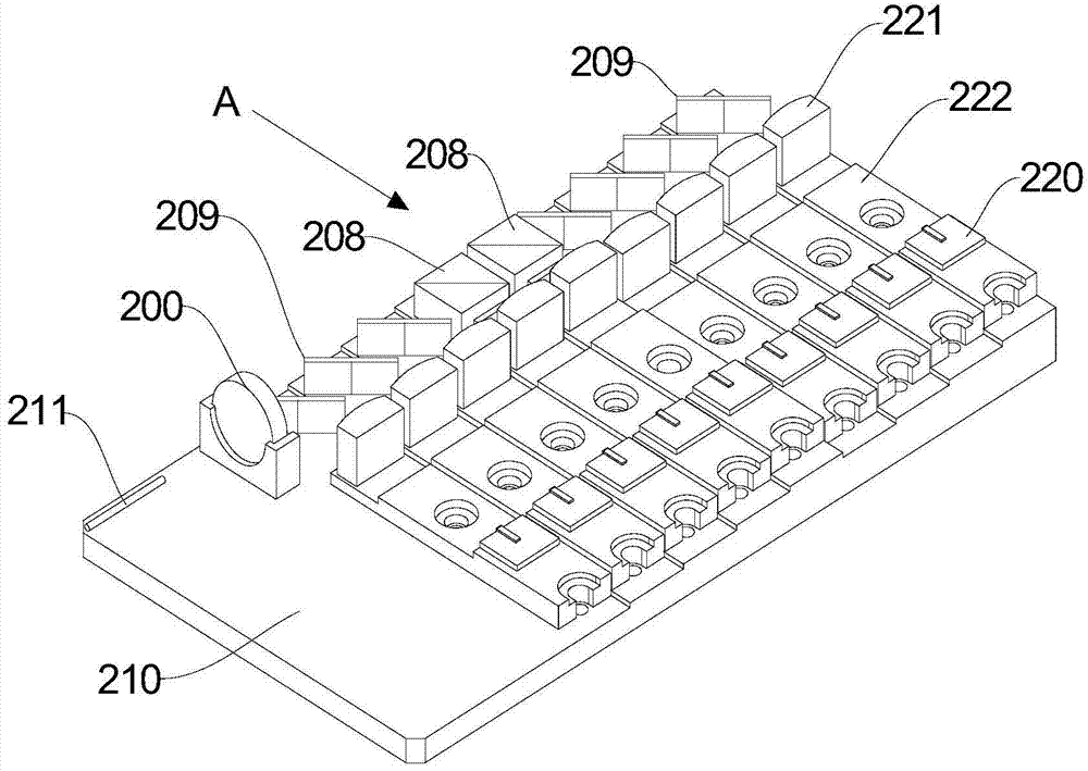
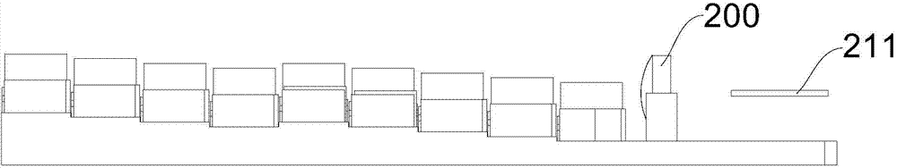
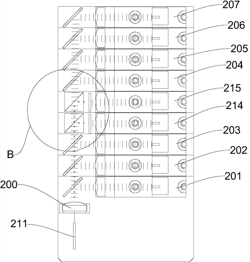
[0059] figure 1 is a schematic structural diagram of Embodiment 1 of the present invention, figure 2 Yes figure 2 A view in direction A, image 3 is a schematic diagram of the optical path of Embodiment 1 of the present invention, Figure 4 Yes Figure 4 The enlarged schematic view of the center B, Figure 5 It is a schematic view of the spatial arrangement of the light spots in front of the coupling mirror in Embodiment 1 of the present invention; Figure 1-5 As shown, Embodiment 1 of the present invention discloses a fiber-coupled semiconductor laser, which includes a coupling mirror 200 and a semiconductor laser module capable of outputting multiple beams of P light and at least one beam of S light.

[0060] The coupling mirror 200 is used to couple multiple beams of P light and at least one beam of S light finally output by the semiconductor laser module into one beam to form converged light; the number of beams of P light is greater than the number of beams of S ligh...

Embodiment 2

[0086] Image 6 It is a structural schematic diagram of Embodiment 2 of the present invention, Figure 7 Yes Figure 7 View from direction C in, Figure 8 It is a schematic diagram of the optical path of Embodiment 2 of the present invention, Figure 9 Yes Figure 9 The enlarged schematic view of the part at D in the center, Figure 10 It is a schematic view of the spatial arrangement of light spots in front of the coupling mirror in Embodiment 2 of the present invention. Embodiment 2 of the present invention discloses a fiber-coupled semiconductor laser, which includes a coupling mirror 300 and a semiconductor laser module capable of outputting multiple beams of P light and at least one beam of S light; the coupling mirror 300 is used to couple the semiconductor laser The module finally outputs multiple beams of P light and at least one beam of S light to be coupled into one beam to form a converged light; the number of beams of P light is greater than the number of beam...


PUM


Abstract

The invention relates to the technical field of lasers, in particular to an optical fiber coupling semiconductor laser device. The optical fiber coupling semiconductor laser device comprises a coupling lens and a semiconductor laser device module capable of outputting a plurality of P light beams and at least one S light beam. The coupling lens is used for coupling the multiple P light beams and the at least one S light beam into a beam to form converged light. The number of the P light beams is larger than the number of the S light beams. In front of the coupling lens, each P light beam corresponds to a P light spot, and each S light beam corresponds to an S light spot. The multiple P light spots are sequentially arranged side by side, and the S light spots are sequentially arranged side by side. Each S light spot corresponds to the corresponding P light spot, each S light spot is coincident with the corresponding P light spot, and the P light spots corresponding to the S light spots are adjacent. The optical fiber coupling semiconductor laser device has the high transmittance and the high coupling efficiency of a space light beam combining mode, and has the high light beam quality of a polarization multiplexing mode.

Description

technical field [0001] The invention relates to the field of laser technology, in particular to a fiber-coupled semiconductor laser. Background technique [0002] At present, there are two main methods to improve the coupling efficiency of fiber-coupled semiconductor lasers by using polarization multiplexing: first, to improve the polarization degree (linear polarization) of the output beam of the semiconductor laser chip (CoS); Transmittance of linearly polarized light. There are certain limitations in improving the coupling efficiency of fiber-coupled semiconductor lasers through the above two approaches. First of all, the polarization degree of the output beam of the semiconductor laser chip cannot be increased to 100%. In addition, every percentage point increase will require great effort and cost, and the waste heat after packaging will cause polarization degradation; on the other hand, the transmittance of polarized light to polarized light cannot reach 100%. The lo...

Claims


Application Information

Patent Timeline
Patent Type & Authority Applications(China)
IPC IPC(8): H01S5/06G02B6/42
Inventor 杨朝栋姜笑尘刘瑞何晓光
Owner BWT BEIJING
Why Eureka
Try Eureka