Permanent-magnet synchronous traction motor for motor train

A traction motor and permanent magnet synchronous technology, applied in the field of electric motors, can solve problems such as unsuitable permanent magnet synchronous traction motors for bullet trains, structural defects of permanent magnet synchronous motors, etc., and achieve improved starting and overload capabilities, power density and utilization of magnet steel Improvement, application of a wide range of effects

Active Publication Date: 2015-07-08
CRRC YONGJI ELECTRIC CO LTD
View PDF8 Cites 6 Cited by
  • Summary
  • Abstract
  • Description
  • Claims
  • Application Information

AI Technical Summary

Problems solved by technology

[0012] The invention solves the problem that the existing permanent magnet synchronous motor is not suitable to be directly used as a permanent magnet synchronous traction motor for a motor vehicle due to structural defects, and provides a permanent magnet synchronous traction motor for a motor vehicle

Method used


Image

  • Permanent-magnet synchronous traction motor for motor train
  • Permanent-magnet synchronous traction motor for motor train
  • Permanent-magnet synchronous traction motor for motor train

Examples


Embodiment Construction

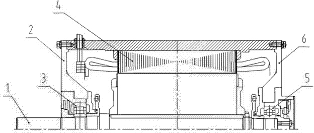
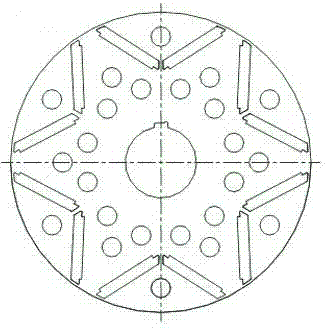
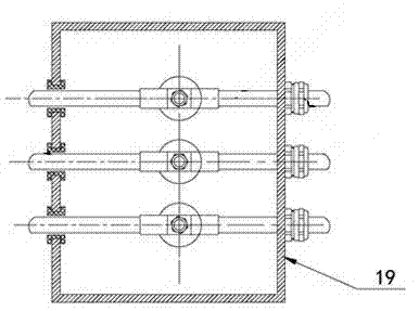
[0026] The permanent-magnet synchronous traction motor for motor vehicles includes a frame with an air inlet 16 on the top, a stator core 4 and a stator coil, a rotor assembly, and a junction box 19; the rotor assembly includes a rotating shaft 1 and a rotor core 11 formed by laminating rotor punches , rotor hold-down ring 8, permanent magnet baffle plate 10, magnetic steel groove 14 and ventilation holes are opened on the rotor punch, and magnetic steel 12 is inserted in the magnetic steel groove; the rotor hold-off ring 8 at the transmission end of the rotor assembly is provided with a ring-shaped rotor The dynamic balance groove is equipped with an inner seal ring labyrinth seal structure, and the permanent magnet baffle plate 10 at the drive end of the rotor assembly is set on the rotating shaft and pressed by the rotor pressure ring 8 . The rotor punching is a U-shaped magnetic circuit structure, that is, three magnetic steel grooves distributed in a U shape form a magneti...


PUM


Abstract

The invention relates to a motor, in particular to a permanent-magnet synchronous traction motor for a motor train. The permanent-magnet synchronous traction motor for the motor train solves the problem that an existing permanent-magnet synchronous motor is not suitable for being directly used as a permanent-magnet synchronous traction motor for a motor train due to structure defects. The motor adopts a novel rotor magnetic circuit structure punching plate, a high-integration compact type rotor structure, a detachable connecting box structure and a lead structure. A connecting box can be conveniently disassembled so that the motor can be installed easily. A U-shaped magnetic circuit permanent magnet structure of an inner rotor is adopted, the magnetic separation bridge and circular bead design is added, and therefore the start and overload capacity of the motor can be improved. A rotor pressing ring at the driving end integrates rotor core pressing, permanent magnet end face pressing, rotor dynamic balancing and an inner seal ring labyrinth seal structure into a whole, the advantages that the structure is compact, the axial occupied space is small, and the installation is convenient are achieved, and the motor can be widely applied in the field of locomotive trains. According to the research, development and the operation of the permanent-magnet synchronous traction motor for the motor train, realistic bases are supplied for the permanent-magnet motor to research and develop a permanent-magnet traction motor structure with higher power, higher rotation speed and higher power density.

Description

technical field [0001] The invention relates to a motor, in particular to a permanent magnet synchronous traction motor for a motor vehicle. Background technique [0002] With the transformation of railway locomotive traction technology from DC drive to AC drive, the requirements for system miniaturization and light weight will come to an end. Low operating cost development. The permanent magnet motor transmission system is more and more favored by users for its high efficiency, energy saving, low noise and low maintenance. The development of a suitable permanent magnet transmission system will become the development direction of railway traction technology in the future. [0003] The load of the motor vehicle traction motor is a wide variable load. In this variable load occasion, it is required to output high efficiency and high power factor under various working conditions of full load and light load. The permanent magnet synchronous motor has high efficiency and power f...

Claims


Application Information

Patent Timeline
Patent Type & Authority Applications(China)
IPC IPC(8): H02K21/12H02K1/27H02K21/02
CPCH02K1/2766H02K5/225H02K21/14H02K2213/03
Inventor 刘荣强孙德强贾喜勤
Owner CRRC YONGJI ELECTRIC CO LTD
Why Eureka
Try Eureka