Microbubble generation device and use thereof

A device for generating micro-bubbles, applied in the direction of dissolution, mixers, chemical instruments and methods, etc., can solve the problems of complex structure and high cost of bubble generation methods, and achieve small pressure drop of equipment, simple structure and good foaming effect Effect

Active Publication Date: 2015-07-15
SHANGHAI INST OF APPLIED PHYSICS - CHINESE ACAD OF SCI
View PDF7 Cites 30 Cited by
  • Summary
  • Abstract
  • Description
  • Claims
  • Application Information

AI Technical Summary

Problems solved by technology

[0004] The technical problem to be solved by the present invention is to overcome the defects of high cost and complex structure of the bubble generation method in the prior art, and provide a microbubble

Method used


Image

  • Microbubble generation device and use thereof
  • Microbubble generation device and use thereof
  • Microbubble generation device and use thereof

Examples


Embodiment 1

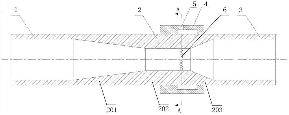
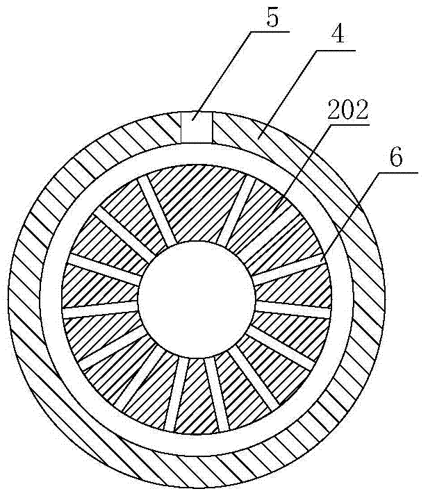
[0033] Such as figure 1 with figure 2 As shown, the microbubble generating device provided in this embodiment includes an input pipeline 1, a venturi tube 2 and an output pipeline 3 connected in sequence; the input pipeline 1, the venturi tube 2 and the output pipeline 3 are on the same straight line; Venturi tube 2 comprises a constriction section 201, a throat section 202 and an expansion section 203 connected in sequence, the input pipeline 1 communicates with the constriction section 201, and the expansion section 203 communicates with the output pipeline 3; the input pipeline 1 and the output pipeline 3 All are equal-diameter straight pipes, the inner diameter of the input pipe 1, the inner diameter of the entrance of the contraction section 201, the inner diameter of the outlet of the expansion section 203 and the inner diameter of the output pipe 3 are the same, and are larger than the inner diameter of the throat section 202. The upper ring of the outer pipe wall of ...

Embodiment 2

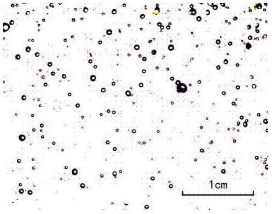
[0038] In this embodiment, the microbubble generating device provided in Example 1 is used to prepare microbubbles in liquid molten salt, wherein the inner diameters of the molten salt delivery pipeline, the input pipeline 1 and the output pipeline 3 of the microbubble generating device are both 50 mm, and the liquid molten salt The flow rate is 20m 3 / h, the number of air holes 6 is 10, the diameter of the air holes 6 is 1mm, the volume percentage of the microbubbles formed in the liquid molten salt is 1% to 5%, and the normal distribution in the liquid molten salt can be obtained Microbubbles with an average diameter of 0.5mm to 3mm, such as image 3 As shown, microbubbles with a diameter of 0.5 mm to 3 mm accounted for more than 80% of the total number of microbubbles.

Embodiment 3

[0040] In this embodiment, the microbubble generating device provided in Example 1 is used to prepare microbubbles in liquid molten salt, wherein the inner diameters of the molten salt delivery pipeline, the input pipeline 1 and the output pipeline 3 of the microbubble generating device are both 50 mm, and the liquid molten salt The flow rate is 20m 3 / h, the number of ventilation holes 6 is 8, the diameter of the ventilation holes 6 is 1mm, and the volume percentage of microbubbles formed in the liquid molten salt is 0.2% to 2%, which can obtain a normal distribution in the liquid molten salt Microbubbles with an average diameter of 0.1mm to 1mm, such as Figure 4 As shown, microbubbles with a diameter of 0.1 mm to 1 mm accounted for more than 90% of the total number of microbubbles.


PUM

PropertyMeasurementUnit
Diameteraaaaaaaaaa
Diameteraaaaaaaaaa

Abstract

The invention discloses a microbubble generation device and a use thereof. The microbubble generation device comprises an input pipe, a Venturi tube and an output pipe, and the three parts are orderly communicated. The input pipe, the Venturi tube and the output pipe are arranged on the same straight line. The Venturi tube comprises a contraction section, a throat section and an expansion section, and the three parts of orderly communicated. The outer pipe wall of the throat section is provided with a ventilation ring. The ventilation ring is a hollow columnar sealed chamber. The columnar body of the hollow columnar sealed chamber is provided with a gas inlet. The pipe wall of the throat section is provided with thorough vents symmetrically distributed along the axle center of the Venturi tube. The cross section formed from the vents is perpendicular to the axis of the Venturi tube. The vents are located in the hollow columnar sealed chamber. The device can uniformly feed gas into a liquid so that micro-bubbles are produced in the liquid. The ventilatory capacity and the number and sizes of the bubbles can be adjusted and effectively controlled by device structure adjustment.

Description

technical field [0001] The invention relates to a microbubble generating device and its application. Background technique [0002] Nuclear energy has increasingly become the main energy source in the world today, accounting for an increasing proportion of energy consumption. However, while using nuclear energy, it also produces a large amount of radioactive substances, which will seriously endanger the survival of human beings. The liquid nuclear reactor coolant contains a large amount of radioactive gases such as krypton, xenon and tritium. Krypton and xenon can easily cause reactor poisoning, and tritium can easily diffuse into the environment through pipeline penetration. A large amount of radioactive tritium is also produced in a heavy water reactor, and most of the radioactive gas is dissolved in heavy water and circulates in the circuit with the coolant. In order to protect the environment and prevent the disorderly diffusion of these radioactive gases, it is necessa...

Claims


Application Information

Patent Timeline
IPC IPC(8): B01F3/04B01F5/04
Inventor 李华刘卫吴胜伟钱渊张宁黄悟真韩兴博
Owner SHANGHAI INST OF APPLIED PHYSICS - CHINESE ACAD OF SCI
Why Eureka
Try Eureka