Method utilizing active carbon to control MBR membrane pollution

A technology of activated carbon and membrane pollution, which is applied in the field of water treatment, can solve the problems of high energy consumption of aeration, and achieve the effects of good processing capacity, reduced space and easy operation

Inactive Publication Date: 2015-07-15
XIAMEN UNIV
View PDF23 Cites 10 Cited by
  • Summary
  • Abstract
  • Description
  • Claims
  • Application Information

AI Technical Summary

Problems solved by technology

However, when MBR is added with suspending filler (carrier), in order to achieve a good mixing effect and actually scrub the membrane surface, it is necessary to increase the aeration intensity accordingly, which brings a new problem of high aeration energy consumption.

Method used


Image

  • Method utilizing active carbon to control MBR membrane pollution
  • Method utilizing active carbon to control MBR membrane pollution

Examples


Embodiment 1

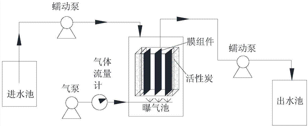
[0018] Example 1: Use 2 sets of the same 75L flat membrane submerged MBR reactor, the effective working volume is 62L, the filter membrane material is PES, the pore diameter is 0.04μm, and the membrane area is 0.5m 2 , a total of 6 pieces, continuous aeration 2L / min, inoculated activated sludge MLSS3000mg / L, influent COD 2900mg / L, effluent peristaltic pump speed controlled at 5rpm, one of which is as figure 1 , The surface of the filter membrane is fixed with a box-type filter screen for activated carbon layer (thickness 1cm, activated carbon average particle size 2.8mm). The 2 sets of MBR have been continuously operated for 40 days, and the COD removal rate is above 95%, and the MBR membrane flux without activated carbon is reduced to 1.44L / (m 2 h), while the flux of the MBR membrane with activated carbon layer is maintained at 10.5L / (m 2 h).

Embodiment 2

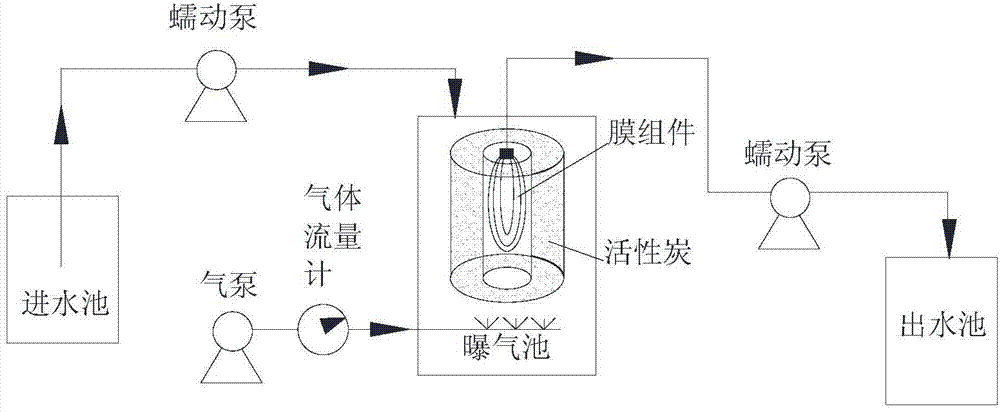
[0019] Example 2: Use 2 sets of the same 10L hollow fiber membrane submerged MBR reactor, the effective working volume is 6L, the filter membrane material is PVDF, the pore diameter is 0.1μm, and the total area of ​​the membrane filament is 0.15m 2 , continuous aeration 2L / min, inoculated activated sludge MLSS3000mg / L, antibiotic sulfamethoxazole 10mg / L in the influent water, and the speed of the effluent peristaltic pump is controlled at 5rpm, one of which is as figure 2 , The surface of the filter membrane is fixed with a circular column type filter screen (thickness 2cm, activated carbon average particle size 5mm). Two sets of MBRs were operated continuously for 60 hours, the MBR sulfamethoxazole without activated carbon was not removed, and the membrane flux was reduced to 6.4L / (m 2 h), while the MBR sulfamethoxazole with activated carbon layer is not removed more than 90%, and the membrane flux remains at 16.8L / (m 2 h).

[0020] For plate-type membrane modules, activat...


PUM

PropertyMeasurementUnit
particle diameteraaaaaaaaaa

Abstract

The invention discloses a method utilizing active carbon to control MBR membrane pollution, and relates to the field of water treatment. Active carbon particles are fixed on the filter membrane of a MBR membrane module, the MBR membrane module is composed of flat membranes or hollow fiber membranes: (1) if the MBR membrane module is composed of flat membrane, the active carbon particles are covered on the surface of the filter membrane to form a flat particle layer, the method comprises the following steps: preparing a dual-layer screen cage from rigid stainless steel screen, filling active carbon particles into the screen cage, placing the screen cage on the surface of the flat membrane; or the flat particle layer is prepared by the following steps: adhering the active carbon particles together by an adhesive to form a flat box shape, and then fixing the flat box on the surface of the flat membrane; (2) if the MBR membrane module is composed of hollow fiber membrane, the active carbon particles are filled in the filter membrane to form an annular cylindrical structure, the method comprises the following steps: preparing a screen cage from rigid stainless steel screen, filling active carbon particles into the screen cage, and finally inserting the screen cage into hollow fiber membrane; or the adhering the active carbon particles together by an adhesive to form a hollow cylinder, and then fixing the hollow cylinder on the exterior of hollow fiber filaments.

Description

technical field [0001] The invention relates to water treatment, in particular to a method for controlling MBR membrane fouling by using activated carbon. Background technique [0002] Membrane Bio-Reactor (MBR for short) is a new type of water treatment technology that combines membrane separation technology and biotechnology. Over the past 20 years, MBR technology has grown exponentially as it offers the advantages of smaller volumes, higher quality treated effluent and better process control over traditional wastewater treatment processes. The increasingly stringent regulations related to sewage treatment and the huge demand for equipment for wastewater reuse stimulate the development of MBR. [0003] The removal of pollutants by MBR is mainly carried out by the degradation of microorganisms and the interception and filtration of filter membranes. The solute and macromolecules are adsorbed and deposited on the membrane surface or in the membrane pores due to hydraulic a...

Claims


Application Information

Patent Timeline
Patent Type & Authority Applications(China)
IPC IPC(8): C02F3/02C02F3/12B01D69/02B01D67/00
CPCY02W10/10
Inventor 沈亮李家鹏袁霞何宁王远鹏卢英华
Owner XIAMEN UNIV
Why Eureka
Try Eureka