
System and method for freezing resistance of cooling tower in winter by utilizing indirect evaporative cooling

A technology of evaporative cooling and evaporative cold water, applied in water shower coolers, direct contact heat exchangers, heat exchanger types, etc., can solve cooling tower icing, cannot prevent cooling tower icing, and does not increase the inlet air temperature and other issues to achieve the effect of avoiding freezing

Active Publication Date: 2015-07-15
TSINGHUA UNIV
View PDF15 Cites 11 Cited by
  • Summary
  • Abstract
  • Description
  • Claims
  • Application Information

AI Technical Summary

Problems solved by technology

[0006] However, the above antifreeze measures cannot fundamentally solve the problem of cooling tower icing.
Adding a windshield device, although the air intake volume and direction have been changed, the air intake temperature is still below 0°C, and there is a possibility of freezing at the air intake; adding a protective thermal water curtain will make the water distribution more uniform, thereby improving the air intake In the case of more wind and less water, but the temperature of the inlet air is not increased; adding electric heat to the cooling water pipe ensures that the cooling water pipe does not freeze, but it cannot prevent the cooling tower from freezing; the fan is periodically reversed as a kind of melting Ice measures do not prevent cooling towers from freezing
[0007] This patent application proposes an indirect evaporative cooling tower antifreeze system and method. By changing the original process structure of the cooling tower, the inlet air temperature can be increased to above 0°C, so that the temperature in the cooling tower can be maintained above 0°C. Fundamentally solve the problem of cooling tower icing

Method used


Image

  • System and method for freezing resistance of cooling tower in winter by utilizing indirect evaporative cooling
  • System and method for freezing resistance of cooling tower in winter by utilizing indirect evaporative cooling

Examples


Embodiment 1

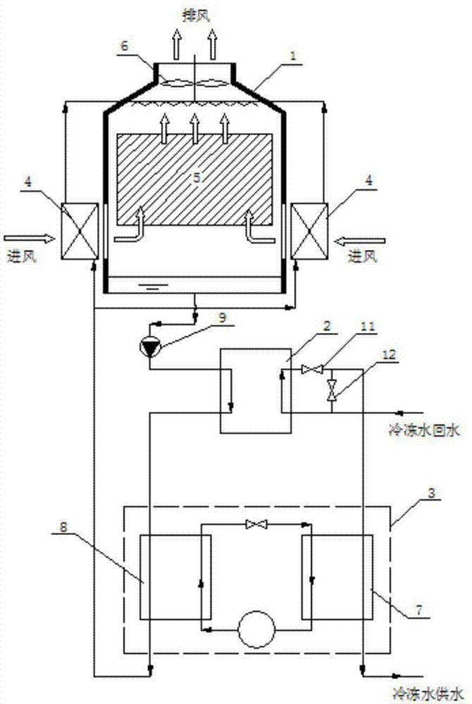
[0027] The composition and connection of the system are as figure 1 Shown:

[0028] The system consists of three parts: an indirect evaporative cooling tower 1, a plate heat exchanger 2, and a vapor compression chiller 3. The lower two sides of the indirect evaporative cooling tower 1 are air-water surface coolers 4, and a packed tower 5 is fixed inside. An exhaust fan 6 is installed at the outlet, and the packed tower 5 consists of a spray system, a packing area and a liquid storage area from top to bottom; a system circulation pump 9 is installed on the pipe at one end of the plate heat exchanger 2, which is connected to the bottom of the liquid storage area. The water port is connected, and the other end is connected to the condenser 8 of the vapor compression refrigerator 3. The water outlet of the condenser 8 is connected to the air-water surface cooler 4, and then connected to the spray system of the packed tower to form a loop. The outer wall pipe on the same side of the p...

Embodiment 2

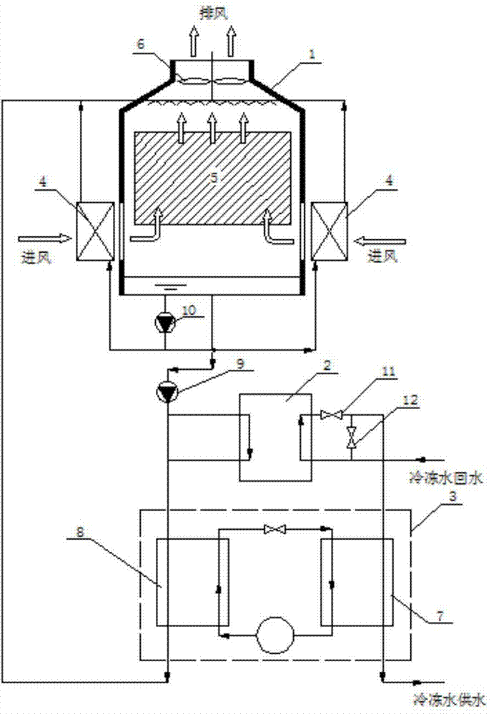
[0031] The composition and connection of the system can also be as figure 2 Shown:

[0032] The difference from Embodiment 1 is that the indirect evaporative cooling tower 1 is equipped with a cold water circulating pump 10, and the bottom water outlet pipeline of the liquid storage area is divided into two branches, one is connected to the air-water surface cooling through the cold water circulating pump 10 4, and then connected to the spray system; one connected to the user's heat exchange end, followed by the system circulating pump (9), plate heat exchanger 2, vapor compression refrigerator 3 condenser 8 connected directly to the outlet of the condenser Into the spray system of packed tower 5.

[0033] During operation, the water sprayed at the top of the tower is divided into two parts after evaporative cooling in the packed tower 5. One part enters the air-water surface cooler 4 under the action of the cold water circulating pump 10 to heat the air inlet, and the other part...

Embodiment 3

[0035] figure 1 with figure 2 The two described systems and methods for using indirect evaporative cooling to achieve winter antifreeze of cooling towers are adjusted throughout the year by adjusting the first valve 11 and the second valve on the chilled water side without switching the pipeline on the cooling water side 12.

[0036] In summer conditions, the first valve 11 is closed and the second valve 12 is opened. The chilled water return water passes through the evaporator 7 of the vapor compression refrigerator 3 to be cooled, and the cooling water prepared by the indirect evaporation chiller 1 passes through the plate heat exchanger 2 Enter the condenser 8 of the vapor compression refrigerator 3, take away the condensation heat, and enter the indirect evaporative chiller 1 for recooling.

[0037] In winter conditions, the vapor compression chiller 3 is closed, the indirect evaporative chiller 1 is used as an independent cold source, the first valve 11 is opened, and the se...


PUM


Abstract

The invention discloses a system and a method for freezing resistance of a cooling tower in winter by utilizing indirect evaporation cooling, belonging to the technical field of evaporation cooling. The system comprises three parts, namely an indirect evaporation cooling tower, a plate-type heat exchanger, and a vapour compression type refrigerator, wherein the indirect evaporation cooling tower comprises air-water surface type coolers, a cooling water circulation pump, a filler tower and an exhaust fan, the stock solution area of the filler tower is connected with the plate-type heat exchanger and a condenser of the vapour compression type refrigerator in sequence through a system circulation pump, and then returns to a spraying system of the filler tower. The system can be operated in summer, winter and a transition season, according to the outside temperature, a first valve and a second valve at the cooling water side are regulated, and the condition that the temperature in the cooling tower is kept to be more than 0 DEG C can be ensured, so that the system can be operated steadily all year.

Description

Technical field [0001] The invention belongs to the technical field of evaporative cooling, and specifically relates to a system and method for realizing antifreezing of a cooling tower in winter by using indirect evaporative cooling. Background technique [0002] In the cold and severe cold regions in the north, the average temperature in winter is lower than 0℃, and the phenomenon of cooling tower icing is very serious. The current antifreeze technologies mainly include the following: [0003] Add a windshield device to adjust the air intake and wind direction to achieve the purpose of antifreeze. Patent CN202501793U discloses an antifreeze wind deflector for electric cooling towers. Through the improvement of the wind deflector structure, the problem that the integral wind deflector cannot change the height of the wind deflector and affects the efficiency of the cooling tower is solved. Patent CN101881573A discloses an antifreeze polymer wind deflector for cooling towers, and a...

Claims


Application Information

Patent Timeline
IPC IPC(8): F28C1/16
Inventor 谢晓云江亿冯潇潇
Owner TSINGHUA UNIV
Learn More