
Secondary Shear Method for Determination of Performance Parameters of Polymer Solutions for Oil Displacement

A polymer solution and polymer technology, applied in the direction of DC flow characteristics measurement, etc., can solve the problems of actual value gap, only suitable for simulating the shear at a certain point in the formation, and cannot fully reflect all shear, etc., to achieve performance Accurate parameters, solving time-consuming and laborious on-site measurement, and wide application range

Active Publication Date: 2018-01-12
SOUTHWEST PETROLEUM UNIV
View PDF6 Cites 0 Cited by
  • Summary
  • Abstract
  • Description
  • Claims
  • Application Information

AI Technical Summary

Problems solved by technology

Among them, the shearing of the polymer solution by the WARING agitator is pure mechanical shearing, which is different from the shearing mode of the polymer solution in the formation, and the shearing of the polymer solution does not conform to the actual situation of the reservoir; However, the shearing of the polymer solution by the near-wellbore simulation experiment device is in line with the reality of the near-wellbore formation, but it can only simulate the shearing of the polymer solution in the near-wellbore formation, and cannot fully reflect the polymerization. The shearing of the polymer solution can be simulated by core shearing to a certain extent, but the shear rate that can be simulated by this shearing method is not continuously changing, and it is only suitable for simulating a certain point in the formation. cut
[0004] To sum up, the current shearing methods involved in indoor simulation are all carried out under a single shearing mode, which cannot fully reflect the shearing experienced by the polymer solution during the injection process. There is still a certain difference between the actual values

Method used


Image

  • Secondary Shear Method for Determination of Performance Parameters of Polymer Solutions for Oil Displacement
  • Secondary Shear Method for Determination of Performance Parameters of Polymer Solutions for Oil Displacement
  • Secondary Shear Method for Determination of Performance Parameters of Polymer Solutions for Oil Displacement

Examples


Embodiment

[0060] Taking a certain oil field as an example below, the two-stage shearing experimental method for measuring the performance parameters of the polymer solution for oil displacement provided by the present invention is specifically introduced:

[0061] In this embodiment, the experimental apparatus and materials are as follows:

[0062] (1) Viscometer: Brookfield DV-Ⅲ viscometer, produced by American Brookfield Company. Test conditions: the shear rate is 7.34s -1 ; The test range of different types of rotors is shown in Table 3.

[0063] Table 3 Viscosity measurement range of different spindles

[0064] rotor

00#

61#

62#

63#

31#

Speed(r / min)

6

18.5

18.8

27.3

21.6

[0065] Shear rate (s -1 )

7.34

7.37

7.4

7.35

7.34

Viscosity Range (mPa·s)

0~100

100~320

100~1500

>1500

100~1389

[0066] (2) Electronic balance: range 20g ~ 3000g, precision 0.01g;

[0067] (3) Constant tem...


PUM

PropertyMeasurementUnit
lengthaaaaaaaaaa
lengthaaaaaaaaaa

Abstract

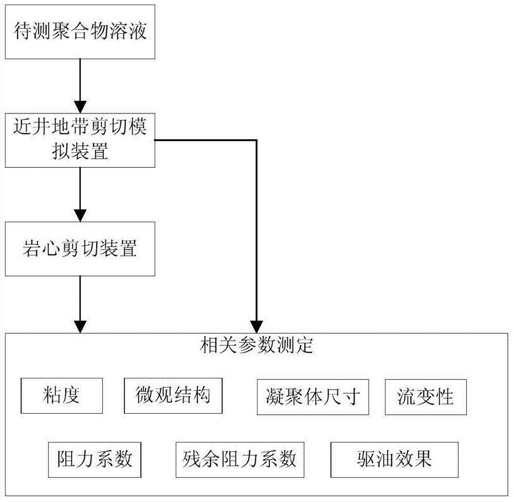
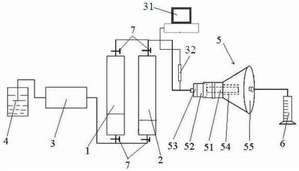
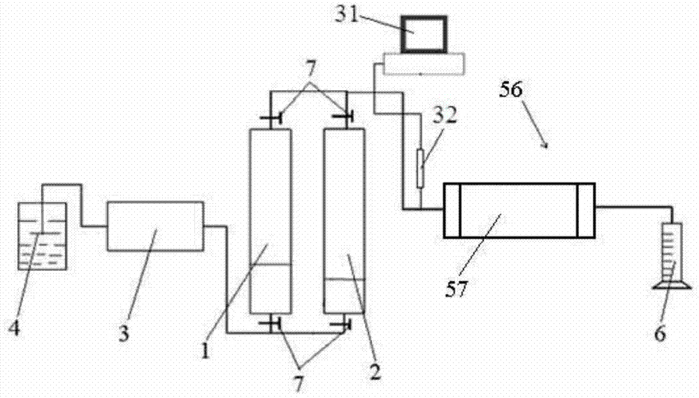
The invention relates to a two-stage shearing method for measuring the performance parameters of a polymer solution for oil displacement, comprising the following steps: 1) preparing the polymer solution a0 to be tested, wherein the polymer solution a0 to be tested is oilfield water and polymer dry powder A solution mixed in any proportion; 2) The polymer solution a0 is sheared at the first stage by using a shear simulation device near the wellbore to obtain the polymer solution a1 after the first stage shear, and the viscosity of the polymer solution a1 is measured , aggregate size, microstructure, rheological properties, resistance coefficient, residual resistance coefficient, and oil displacement effect; 3) The polymer solution a1 is subjected to second-stage shearing by using a core shear simulation device to obtain After the polymer solution a2, measure the viscosity, aggregate size, microstructure, rheological properties, drag coefficient, residual drag coefficient, and oil displacement effect of the polymer solution a2.

Description

technical field [0001] The invention relates to an experimental method for measuring the performance parameters of the polymer solution for oil displacement, in particular to a secondary shear method for measuring the performance parameters of the polymer solution for oil displacement. Background technique [0002] With the continuous development of economies around the world, the demand for oil and gas resources is also increasing day by day. In the absence of more proven oil and gas reserves, enhancing oil and gas recovery is the only effective way. Polymer flooding is the most widely used method in enhancing oil recovery. Improve oil recovery by injecting polymer solution into the formation to improve mobility ratio and increase swept volume. The biggest problem faced in the process of polymer solution injection into the formation is shear degradation. The shear degradation of the polymer solution directly leads to the degradation of the performance of the polymer solut...

Claims


Application Information

Patent Timeline
Patent Type & Authority Patents(China)
IPC IPC(8): G01N11/08
Inventor 舒政王迈叶仲斌施雷庭卢强陈洪曹杰
Owner SOUTHWEST PETROLEUM UNIV
Learn More