Method for testing single event effect of on-chip system

A single-event effect, system-on-chip technology, applied in the direction of measuring electricity, measuring devices, measuring electrical variables, etc., can solve the problems of complex measurement methods, no unified test method for single-event effect testing, and complex error types, and achieve data processing. The effect of convenient, convenient and quick detection and high degree of automation

Inactive Publication Date: 2015-07-22
XI AN JIAOTONG UNIV
10 Cites 12 Cited by

AI-Extracted Technical Summary

Problems solved by technology

However, the size of semiconductor devices is getting smaller and the operating voltage is getting lower and lower, which means that single event effects are more likely to occur, and the system on chip integrates multiple functional m...

Abstract

The invention discloses a method for testing single event effect of an on-chip system. The method includes: dynamically testing single event effect of a register, a high-speed data cache D-cache, an integer operation unit ALU, a floating-point operation unit FPU, direct memory access DMA, an off-chip memory, an on-chip memory and a peripheral unit in a microprocessor of the on-chip system; mainly testing the above function modules dynamically, namely testing occurrence number of single event effect, error data and working current changing condition of the function modules in irradiation environment. By the method, single event effect of different function modules inside the on-chip system can be tested online accurately.

Application Domain

Technology Topic

Single effectDirect memory access +10

Image

  • Method for testing single event effect of on-chip system
  • Method for testing single event effect of on-chip system
  • Method for testing single event effect of on-chip system

Examples

  • Experimental program(1)

Example Embodiment

[0054] The present invention will be further described in detail below in conjunction with the accompanying drawings and specific embodiments.
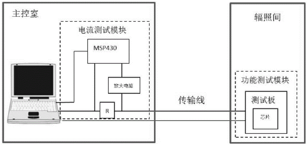
[0055] like figure 1 As shown, several components of the test method of the present invention are illustrated, including the upper computer control unit, the current test module and the lower computer SoC test board. The computer in the main control room in the figure runs the upper computer control software. The current detection unit mainly amplifies the voltage on the sampling resistor R through the amplification circuit, and then converts the voltage through the MSP430 single-chip microcomputer to obtain the working current value after conversion. The test board is located in the irradiation room, and the irradiation source is perpendicular to the SoC chip during the test.
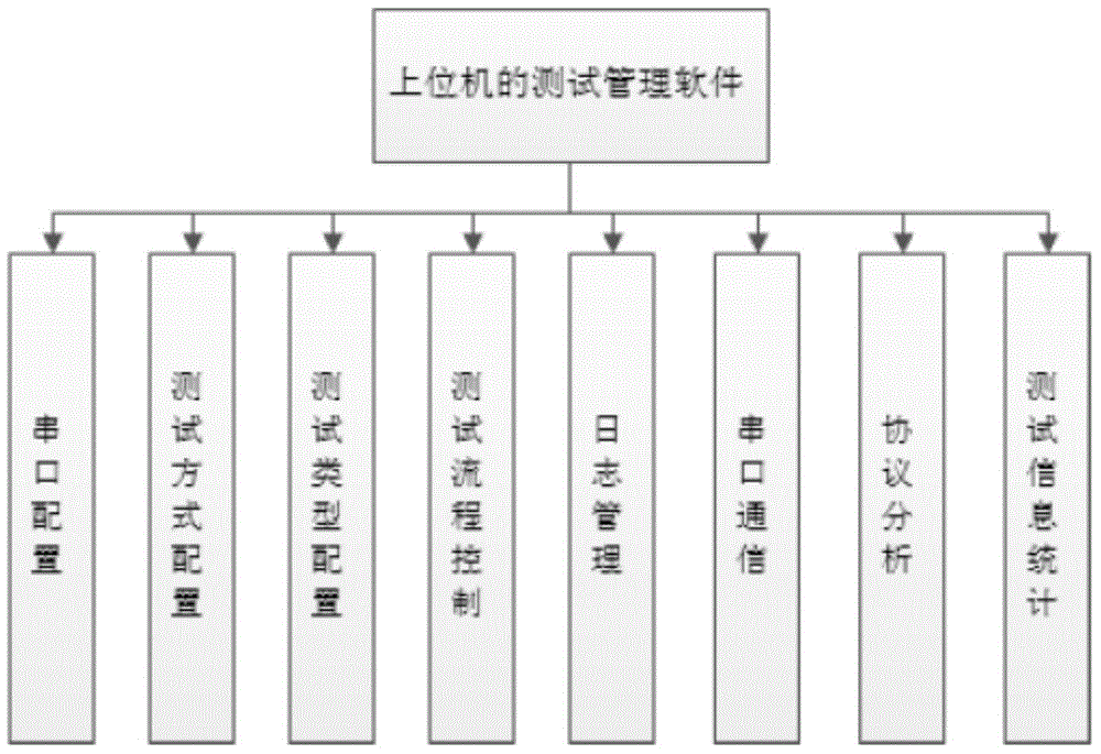
[0056] like figure 2 Shown are several main functions of the host computer management software. Including serial port configuration, test mode configuration, test type configuration, test process control, log management, serial port communication, protocol analysis and test information statistics. Configure the test board of the lower computer through the upper computer software, and select the test method, including the test module and the number of tests. The host computer controls the entire test process, and after the test is over, the test results are automatically saved in the log.
[0057] like image 3 As shown, it is the control flow of the system-on-chip single event effect testing method of the present invention:
[0058] Step 1: Set up the test system before the irradiation test, including the host computer and current test module set in the main control room and the functional test template set in the irradiation room. The current test module includes MSP430, amplifier circuit and sampling Resistor R, the functional test template includes a SoC test board and a chip; the current test module mainly amplifies the voltage on the sampling resistor R through an amplifying circuit, and then converts it into a current value through AD conversion and corresponding operations; the host computer Connect the USB-UART line of the test board through the USB extension line, and connect the sampling resistor R to the +5V power line inside the USB extension line. Relevant calculations, and finally output the current value on the host computer software;
[0059] Step 2: Select the test module and the number of times of the test by the host computer, the test module includes registers in the system-on-chip microprocessor, high-speed data cache D-cache, integer arithmetic unit ALU, floating-point arithmetic unit FPU, direct memory access DMA, off-chip and on-chip memory, and peripheral units; cyclically test one or more of the above-mentioned test modules in the system-on-chip during the irradiation process;
[0060] Step 3: Check whether the function of the test module is normal, and all test results are saved in the log, including the current value;
[0061] Step 4: Stop the test when the irradiance fluence or the cumulative number of single event effects occurs reaches the requirement (until the number of errors exceeds 100 or the irradiance fluence exceeds 1×10 7 piece/cm 2 );
[0062] Step 5: Open the log and count the error results.
[0063] like Figure 4 As shown, it is the function of the test software of the lower computer test board, which is mainly the test content of a system-on-chip single event effect test method, including registers, high-speed data cache (D-Cache), integer arithmetic unit (ALU), Floating-point unit (FPU), direct memory access (DMA), off-chip and on-chip memory, programmable logic, and peripheral units. like figure 1 As shown, the components of the entire test system. Implement dynamic testing for each module.
[0064] The single event effect test of the register is a dynamic test, which includes the following steps: save the initial value of the register under test to the external memory during the test; perform an assignment operation on the register under test during irradiation, and save the current value of the register after the assignment is completed. In the external memory; compare the value of the tested register in the external memory with the assigned value; if the values ​​are inconsistent, it means that a single event event has occurred; after a test is completed, return to the initial value of the register. The test is executed in a loop until the number of errors or the irradiance fluence reaches the requirement and the test is stopped. For example, this method is used to test the general-purpose registers such as R0, R1, R2, R3, R4, R5, R6, R7, R8, R9, R10, R11, R12 and R14 in the ARM core of Xilinx Zynq-7010SoC. The test process is: save the initial value of the register during the running of the program; load 0xFF to these registers, that is, write the value; read and save the value of the test register in the external memory; compare the value of the register in the external memory with the assigned value Value; return the initial value of the register after the test, and record the test result.
[0065] For the high-speed data cache (D-Cache) single event effect test in the system on chip, assign a value to the high-speed data cache D-Cache during irradiation, and save the data in the high-speed data cache D-Cache to the external memory after the assignment is completed, and then Change the data in the high-speed data cache D-Cache, invalidate the current data in the high-speed data cache D-Cache, and then return the data stored in the external memory to the high-speed data cache D-Cache. This test detects the main functions of the high-speed data cache D-Cache, and judges whether the high-speed data cache D-cache is normal. For example, when testing the high-speed data cache D-cache in Xilinx Zynq SoC, you can use the Cache Flush and Cache Invalid instructions to test the writing and reading functions of the high-speed data cache D-cache.
[0066] Integer operation unit (ALU) single event effect test, perform mathematical operations, logical operations, shift operations, etc. on the integer operation unit (ALU) during the irradiation process, compare the operation results of the integer operation unit (ALU) before and after irradiation, record Errored data and number of errors.
[0067] Floating point unit (FPU) single event effect test, perform fast Fourier transform (FFT) test, check test results before and after irradiation, record error data and error times.
[0068] On-chip and off-chip memory single event effect test, during irradiation, assign values ​​to the memory within the specified address range. For the on-chip memory, part of the storage space can be assigned, and the off-chip memory can be fully assigned; read out the values ​​​​in the memory for comparison ; Statistics of error data and error addresses. For example, the Xilinx Zynq-7010SoC chip can test the core 64KB of the on-chip 256KB memory and the off-chip 1G memory. During the test, each address is assigned 0xFFFFFFFF or 0xAAAAAAAA, compared with writing and reading, and counting the results.
[0069] Direct memory access (DMA) single event effect test, including the following steps: Initialize all channels in the direct memory access DMA, divide the external memory into 2 data storage areas of the same size; one of the storage areas is filled with known data ;Open DMA to transfer data to another storage area; compare the values ​​in the two storage areas, and count the error data. For example, Xilinx Zynq-7010SoC chip, open the 8 channels of DMA, realize the transfer of data from memory to memory, and check the wrong data in the irradiation process.
[0070] Peripheral single event effect test is mainly to check whether the peripheral is working normally by assigning values ​​to the control registers of different peripherals and then reading the return value.
[0071] The watchdog timer is turned on in the test system. When the program terminates or the system crashes during the system test, it can be automatically reset and the test will be restarted.
[0072] The above embodiments are only used to illustrate the present invention, but not to limit the present invention. Those of ordinary skill in the relevant technical field can make various changes and modifications without departing from the spirit and scope of the present invention. Therefore, all Equivalent technical solutions also belong to the category of the present invention, and the patent protection scope of the present invention should be limited by claims.

PUM

no PUM

Description & Claims & Application Information

We can also present the details of the Description, Claims and Application information to help users get a comprehensive understanding of the technical details of the patent, such as background art, summary of invention, brief description of drawings, description of embodiments, and other original content. On the other hand, users can also determine the specific scope of protection of the technology through the list of claims; as well as understand the changes in the life cycle of the technology with the presentation of the patent timeline. Login to view more.

Similar technology patents

Pressure-balancing valve for irrigation system

Owner:INST OF GENETICS & DEVELOPMENTAL BIOLOGY CHINESE ACAD OF SCI

Classification and recommendation of technical efficacy words

  • High degree of automation
  • Easy connection

Full-automatic flexible assembly line of light emitting diode (LED) bulb lamp

InactiveCN102896494AIncreased reliability and automationHigh degree of automationAssembly machinesLight sourceStructure based
Owner:SHANGHAI RADIO EQUIP RES INST

Wheelchair holding device

InactiveUS7455490B1Reduces manual laborEasy connectionItem transportation vehiclesWagons/vansEngineeringWheelchair
Owner:IRWIN SEATING

In-wheel motor with brake

ActiveUS20140159468A1Easy connectionSufficient spaceSpeed controllerElectric devicesStatorBraking system
Owner:E TRACTION EURO BV
Why Eureka
Try Eureka