Hole machining device

A hole processing and tapered hole technology is applied in the field of electric heating plate production and processing equipment, which can solve the problems affecting the performance of mica materials, the bulge of the material in and out, and the wire drawing, so as to facilitate the drilling quality, improve the drilling performance, The effect of increasing stiffness

Inactive Publication Date: 2015-07-29
CHENGDU YANGZHONG NEW ENERGY TECH
View PDF7 Cites 3 Cited by
  • Summary
  • Abstract
  • Description
  • Claims
  • Application Information

AI Technical Summary

Problems solved by technology

[0004] In order to solve the above-mentioned problems such as material delamination, threading, roughening, bulging of materials in and out, and rough surface of holes in the process of processing mica material fastener holes, which affect the performance of mica materials, the present invention provides a Seed hole processing device

Method used


Image

  • Hole machining device

Examples


Embodiment 1

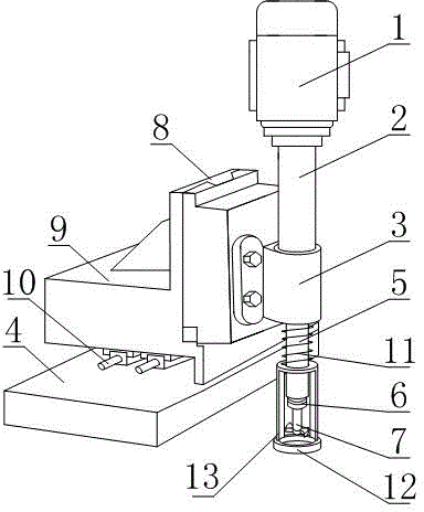
[0022] Such as figure 1 , a hole processing device, comprising a motor 1, a rotating shaft 5, a drill clamp 6 and a drill bit 7, the drill clamp 6 is fixedly connected to the rotating shaft 5 of the motor 1, the drill clamp 6 is held on the drill clamp 6, and also includes The mica board compacting part, the vertical lifting system and the horizontal knife system, the mica board compacting part includes a compacting spring 11 and a compacting plate 12, and the compacting spring 11 is sleeved on the rotating shaft 5 , and one end of the compression spring 11 is fixed on the housing of the motor 1, and the other end of the compression spring 11 is fixedly connected with the tight pressing plate 12, and the tight pressing plate 12 is located in the radial direction of the drill bit 7, and the tight pressing plate 12 is also provided with a through hole positioned on the axial direction of the drill bit 7, the through hole is a tapered hole, and the larger end of the tapered hole ...

Embodiment 2

[0026] This embodiment makes the following further limitations on the basis of Embodiment 1: As shown in Figure 1, in order to realize that the motor 1 is far away from the drilling area of ​​the mica plate, it is convenient to clamp and fix the present invention or manually hold and fix, which is beneficial to the rotating shaft. 5 rigidity, also includes the tubular shaft sleeve 2, the shaft sleeve 2 and the rotating shaft 5 gap fit, one end of the shaft sleeve 2 is fixed on the housing of the motor 1, and the compression spring 11 is fixed on the other end of the shaft sleeve 2 Connected to the casing of the motor 1. Preferably, in this structure, the shaft sleeve 2 is embedded with a bearing, that is, the rotating shaft 5 is connected to the shaft sleeve 2 through a bearing. In this embodiment, a fixed seat 3 protruding relative to the shaft sleeve 2 is provided on the shaft sleeve 2 , and the compression spring 11 is connected to the shaft sleeve 2 through the fixed seat ...

Embodiment 3

[0030] This embodiment makes the following further improvements on the basis of any of the above embodiments: figure 1 As shown, in order to avoid indentation caused by excessive local stress on the mica plate when the surface of the mica plate contains granular impurities, a flexible pad is provided on the side of the compact pressing plate 12 away from the motor 1 .

[0031] As a simple and easy-to-process structure, the horizontal tool feed system includes a base 4, a feed roller 10, and a feed table 9, and the feed roller 10 is located in a guide rail arranged on the base 4, and the feed The bottom surface of the table 9 is connected to the feed roller 10;

[0032] The vertical lifting system includes a lifting platform 8 and a brake device for braking the lifting platform 8 to perform lifting movement. The lifting platform 8 is connected to the side of the feeding platform 9 through a dovetail groove, and the motor 1 is fixed on the lifting platform 8 , the braking devic...


PUM


Abstract

The invention discloses a hole machining device. The hole machining device comprises a motor, a rotating shaft, a drill bit clamp, a drill bit, a mica plate compacting and compressing part, a vertical lifting system and a horizontal feed system, wherein the drill bit clamp is fixedly connected to the rotating shaft of the motor; the drill bit is clamped on the drill bit clamp; the mica plate compacting and compressing part comprises a compression spring and a compacting and pressing plate; the compression spring sleeves the rotating shaft; one end of the compression spring is fixed to a shell of the motor; the other end of the compression spring is fixedly connected with the compacting and pressing plate; the compacting and pressing plate is positioned in the radial direction of the dill bit; a through hole positioned in the axial direction of the drill bit is also formed in the compacting and pressing plate and is a conical hole; the relatively big end of the conical hole is close to the motor; the vertical lifting system is arranged on the horizontal feed system; the motor is fixed to the vertical lifting system and the horizontal feed system. The hole machining device is simple in structure, and the mica plate hole machining quality is improved.

Description

technical field [0001] The invention relates to a production and processing equipment for an electric heating plate, in particular to a hole processing device. Background technique [0002] Carbon crystal, the full name of carbon microcrystal, is a crystal structure of carbon. The chemical properties of elemental carbon are relatively stable at room temperature, insoluble in water, dilute acids, dilute alkalis and organic solvents. Carbon crystals and their compounds are widely used in industrial high-tech and medical high-tech. The carbon in carbon crystal film The crystal composite layer contains carbon nanotubes, modified ball-milled short carbon fibers, resin coatings and infrared emitting powders, which have good anti-oxidation, fresh-keeping and heat insulation effects, and have strong far-infrared radiation, high electrothermal conversion efficiency, It has the characteristics of small surface temperature difference, good corrosion resistance, weather resistance and ...

Claims


Application Information

Patent Timeline
Patent Type & Authority Applications(China)
IPC IPC(8): B28D1/14B28D7/04
CPCB28D1/14B28D7/04
Inventor 李杨忠
Owner CHENGDU YANGZHONG NEW ENERGY TECH
Why Eureka
Try Eureka