

Use of an adhesive composition based on silylated polymers for cryogenic applications
A silylation, polymer technology, applied in the direction of polyether adhesives, polyurea/polyurethane adhesives, adhesive types, etc., can solve the problem of not providing shock-absorbing buffers and absorbing deformation, to prevent harmful the effect of damage
- Summary
- Abstract
- Description
- Claims
- Application Information
AI Technical Summary
Problems solved by technology
Method used
Image

Examples
Embodiment
[0181] Several adhesive compositions of the present invention were prepared and tested.
[0182] Use the following products:
[0183] -PS1: XB502(Wacker);
[0184] -PS2: STP-E15(Wacker);
[0185] -PS3: STP-E10(Wacker);
[0186] -PS4: MS S303H (Kaneka);
[0187] -PS5: 1050MM (Momentive);-
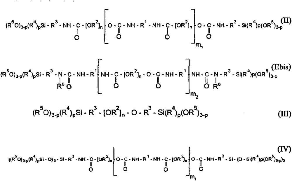
[0188] -PS6: PolymerA described in International Application WO2009 / 106699 (corresponding to the polymer of formula (II) defined above, wherein R 1 stands for isophorone diisocyanate (IPDI);
[0189] - PS7: polymer corresponding to the formula (IIbis) defined above;
[0190] - CM1: Precipitated calcium carbonate with 0.05 μm particle size determination 312 (Solvay);
[0191] - CM2: aluminum hydroxide with 3 μm particle size determination OL104 (Martinwerk);
[0192] -CO1: polyvinyl chloride 373 (Solvay);
[0193] -AO: Antioxidant 1010 (BASF);
[0194] -CH: moisture scavenger XL10 (Wacker);
[0195] -PA: Adhesion promoter GF9(Wacker);
[0196] -Kta1: diazabic...
PUM
| Property | Measurement | Unit |
|---|---|---|
| Granularity | aaaaa | aaaaa |
| Melt viscosity | aaaaa | aaaaa |
| Compression modulus | aaaaa | aaaaa |
Abstract
Description
Claims
Application Information