Fuel conveying method for internal combustion engine using gas-liquid two-phase natural gas as fuel

A technology for internal combustion engines and natural gas, applied in the field of internal combustion engine combustion system construction, can solve problems such as reducing emissions, improving reliability, and disadvantages

Inactive Publication Date: 2015-07-29
SOUTHWEST JIAOTONG UNIV
View PDF5 Cites 1 Cited by
  • Summary
  • Abstract
  • Description
  • Claims
  • Application Information

AI Technical Summary

Problems solved by technology

Therefore, the intake air temperature of the current natural gas engine is high, the heat load of the combustion chamber parts is high, and the NO X It will be generated in large quantities under the condition of high temperature and rich oxygen, so it is not conducive to improving reliability and reducing emissions

Method used


Image

  • Fuel conveying method for internal combustion engine using gas-liquid two-phase natural gas as fuel
  • Fuel conveying method for internal combustion engine using gas-liquid two-phase natural gas as fuel
  • Fuel conveying method for internal combustion engine using gas-liquid two-phase natural gas as fuel

Examples


Embodiment Construction

[0047] The technical content of the present invention will be further described below in conjunction with the accompanying drawings.

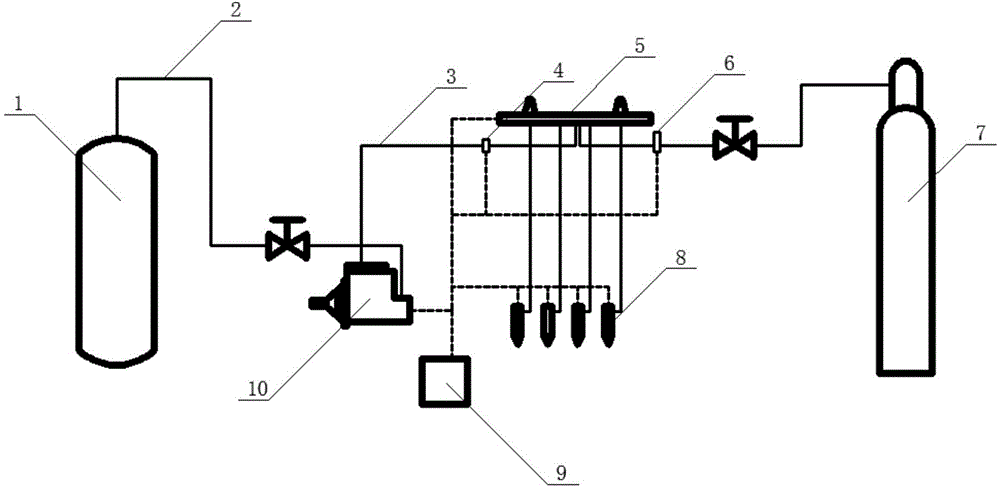
[0048] Such as figure 1 As shown, the gas-liquid two-phase natural gas internal combustion engine combustion system of the embodiment of the present invention is composed of: the fuel entering the adiabatic common rail 5 has two paths: a liquid path and a gas path; The pressure pump 10 is transported to the adiabatic common rail 5; the gas route enters the adiabatic common rail 5 through the gaseous compressed natural gas cylinder 7 through the corresponding pipe valve;

[0049] 2) The fuel mixed by the adiabatic common rail 5 is delivered to the cylinder from the outlet of the adiabatic common rail 5 through the electronically controlled injector 8;

[0050] 3) The liquid circuit and the gas circuit are provided with corresponding pipe valves for connection, and corresponding pressure sensors are provided in the gas circuit; the internal comb...


PUM


Abstract

The invention discloses a fuel conveying method for an internal combustion engine using a gas-liquid two-phase natural gas as the fuel. The method comprises the following steps: conveying a liquid-state compressed natural gas source and a gas-state compressed natural gas source to a heat insulation common rail in a heat insulation manner; mixing the liquid-state compressed natural gas source with the gas-state compressed natural gas source in the thermal insulation common rail, and conveying the mixture into a gas cylinder through an electrically controlled fuel injector; the fuel entering the heat insulation common rail (5) is divided into a liquid route and a gas route; the liquid route is conveyed to the heat insulation common rail (5) by a liquid-state compressed natural gas cylinder (1) through a heat insulation low-pressure pipe (2) and a heat insulation pressure pump (10); and the gas route enters the heat insulation common rail (5) by a gas-state compressed natural gas cylinder (7) through corresponding pipes and valves. The fuel conveying method for the internal combustion engine using the gas-liquid two-phase natural gas as the fuel allows the gas phase natural gas and the liquid phase natural gas to be flashed and boiled upon entering the gas cylinder; and real-time designs and controls of the gas and liquid components of the two-phase natural gas are subjected to different working conditions. Due to the fact that the gas-liquid two-phase natural gas is combusted, the CO emission, the CO2 emission and the PM emission are substantially low, without NMHC. The fuel is injected during the compression process, and accordingly the HC emission is low. The temperature in the cylinder is low; the NOX emission is low; and the emission performance is low.

Description

[0001] Field [0002] The invention relates to a combustion system structure of an internal combustion engine, in particular to a combustion system using natural gas as fuel. Background technique [0003] In the current natural gas internal combustion engine, whether it is the central single-point injection at the intake manifold, the multi-point injection at the intake manifold or the direct injection in the cylinder with the nozzle installed on the cylinder head, the injected fuel is all gaseous natural gas. In a non-direct injection natural gas engine, the calorific value of the mixture of natural gas and air is 12% lower than that of diesel and air; at the same time, natural gas enters the cylinder in a gaseous state, occupying a certain cylinder volume, so that the air intake ratio About 10% less when using liquid fuel. In-cylinder direct-injection natural gas internal combustion engine uses natural gas to enter the cylinder at the end of the intake stroke. Although thi...

Claims


Application Information

Patent Timeline
Patent Type & Authority Applications(China)
IPC IPC(8): F02M21/02F02D41/02F02D41/30
CPCY02T10/30
Inventor 张钊周斌张艺华
Owner SOUTHWEST JIAOTONG UNIV
Why Eureka
Try Eureka