Inner rotor cooling type high-power eddy speed regulator

An inner rotor, high-power technology, applied in the field of inner-rotor cooling high-power eddy current governor, can solve the problems of cooling medium infiltration, lubrication system equipment failure, increased processing difficulty, etc., to facilitate assembly and maintenance, large Power eddy current speed regulation, realize the effect of eddy current speed regulation

Inactive Publication Date: 2015-07-29
HOHAI UNIV
View PDF9 Cites 4 Cited by
  • Summary
  • Abstract
  • Description
  • Claims
  • Application Information

AI Technical Summary

Problems solved by technology

[0008] 1. Although cooling on the outer rotor disk can play a role in heat dissipation, since the heat dissipation mechanism is located on the periphery of the entire speed control mechanism, the speed control mechanism needs to be sealed as a whole, and the sealing requirements are high. The site often brings cooling medium due to sealing problems. Penetration into the lubrication system causing equipment failure
[0009] 2. Although the heat generation of the permanent disk itself is small, the heat conduction and radiation of the conductor disk to the permanent disk through the air also needs to be dissipated;
However, after the assembly of the outer rotor is completed, the adjustment of the inner rotor becomes very difficult due to the complex structure of the inner rotor adjustment mechanism and its location in the closed space enclosed by the outer rotor.
In addition, the complex inner rotor structure also greatly increases the difficulty of processing

Method used


Image

  • Inner rotor cooling type high-power eddy speed regulator
  • Inner rotor cooling type high-power eddy speed regulator
  • Inner rotor cooling type high-power eddy speed regulator

Examples


Embodiment 1

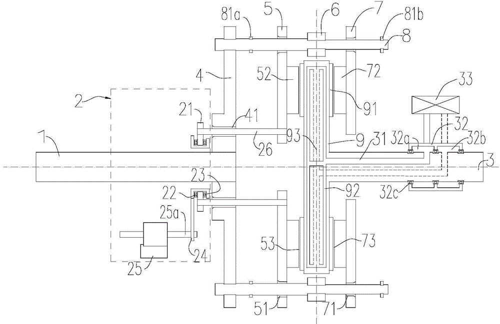
[0045] Such as figure 1 As shown, a high-power vortex speed governor with inner rotor cooling includes an inner rotor, an outer rotor coaxially arranged with the inner rotor, and a coolant supply and discharge system.

[0046] The inner rotor includes an inner rotor shaft 3 , an inner rotor rotating disc 9 and two conductive metal discs 91 .

[0047] A first sealed cavity 92 is provided inside the inner rotor shaft 3 along the axial direction.

[0048] The inner rotor rotating disk 9 is coaxially and fixedly sleeved on the outer periphery of the left end of the inner rotor shaft 3 , and the inner rotor rotating disk 9 is provided with a second sealed cavity 93 along the radial direction. Preferably, the inner rotor rotating disk 9 and the inner rotor shaft 3 are integrally arranged.

[0049] Two conductive metal discs 91 are respectively coaxially fixed on both sides of the inner rotor rotating disc 9, such as Figure 8 As shown, each side of the inner rotor rotating di...

Embodiment 2

[0095] The structure and principle of embodiment 2 are basically the same as embodiment 1, the difference is: as Figure 11 As shown, several groups of disk-shaped planar windings 56 are provided on the right side surface of the first outer rotor moving disk 5 , and several groups of disk-type planar windings 56 are also provided on the left surface of the second outer rotor moving disk 7 .

[0096] Additionally, if Figure 10 As shown, the left side of the first outer rotor moving disk 5 is preferably provided with an annular first cooling fin 57 .

[0097] The right side of the second outer rotor moving disk 7 is preferably provided with an annular second cooling fin 75 .


PUM


Abstract

The invention discloses an inner rotor cooling type high-power eddy speed regulator. The inner rotor cooling type high-power eddy speed regulator comprises an inner rotor, an outer rotor and a cooling liquid feeding and discharging system, wherein the inner rotor comprises an inner rotor shaft, an inner rotor rotating disk and two symmetric electroconductive metal disks, the cooling liquid feeding and discharging system comprises a cooling liquid feeding and discharging pipeline, a cooling liquid collector and an outer heat exchange mechanism, and the outer rotor comprises an outer rotor shaft, two symmetric magnetic outer rotor moving disks and a rotary linear adjusting mechanism. The cooling liquid feeding and discharging pipeline is arranged inside the inner rotor shaft and the inner rotor rotating disk. A changeable air gap is reserved between each outer rotor moving disk and the electroconductive metal disk which are arranged on the same side. After the structure is adopted, the inner rotor is in flexible (magnetic) connection with the outer rotor and is simple in structure, low in processing difficulty and beneficial to assembly and maintenance. The cooling liquid feeding and discharging system is capable of cooling the inner rotor rotating disk maximally and subjecting the outer rotor permanent magnet disks to air convection cooling, so that high-power eddy speed regulation is achieved.

Description

technical field [0001] The invention relates to a speed governor, in particular to an inner rotor cooling type high-power eddy current speed governor. Background technique [0002] The existing permanent magnet eddy current speed regulating device is mainly composed of two parts: a permanent magnet rotor and a copper (or other conductor) rotor. Generally, the shaft of the motor and the shaft of the working machine are respectively connected to one of the rotors. There is an air gap (called an air gap) between the copper rotor and the permanent magnet rotor, and there is no mechanical connection for torque transmission. In this way, a soft (magnetic) connection is formed between the motor and the working machine, and the shaft torque and speed of the working machine can be changed by adjusting the air gap, so it can adapt to various harsh environments, and because there is no direct mechanical connection, the mechanical loss. [0003] In the structure of the existing disc v...

Claims


Application Information

Patent Timeline
Patent Type & Authority Applications(China)
IPC IPC(8): H02K51/00H02K1/27H02K1/32
Inventor 金平王倩雯袁越陈芷群许多江泽南孔祥春林伟伟
Owner HOHAI UNIV
Why Eureka
Try Eureka