Slipping type seamless telescopic device

A seamless telescopic and sliding technology, used in bridge parts, bridges, buildings, etc., can solve the problems of easy damage of long-toothed plates and stainless steel plates, empty tooth ends of long-toothed plates, insufficient waterproof measures, etc., to achieve safety. Performance guarantee, smooth and comfortable driving, and the effect of alleviating rust damage

Inactive Publication Date: 2015-08-05
JSTI GRP CO LTD +1
View PDF8 Cites 13 Cited by
  • Summary
  • Abstract
  • Description
  • Claims
  • Application Information

AI Technical Summary

Problems solved by technology

[0003] The comb-tooth type telescopic device is currently used relatively frequently in some provinces in China. From the perspective of the use effect, the comb-tooth type telescopic device has the following problems: the lower part of the tooth end of the long-toothed plate is hollow, the concrete is not full, and the long-toothed The plate cantilever is stressed, and the long-toothed plate and stainless steel plate are easily damaged; the bolts are not strong enough, and the bolts are fatigued and damaged; the waterproof measures are insufficient, and it is easy to cause serious steel plate corrosion; the comb teeth of the long-toothed plate of the comb-toothed plate telescopic device are warped or missing Phenomenon, when the vertical corner of the beam body occurs, the vertical deformation occurs when the pier sinks, and the phenomenon of warping or missing teeth will occur
The seamless expansion joint has the advantages of short maintenance time, low noise, and good driving comfort, but the device is prone to cracks during use, and the cracks are generally distributed in the center of the cross-slit plate or on the top surface corresponding to both ends

Method used


Image

  • Slipping type seamless telescopic device
  • Slipping type seamless telescopic device

Examples


Embodiment 1

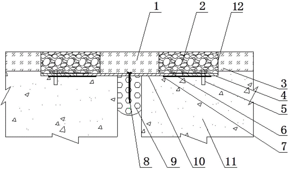
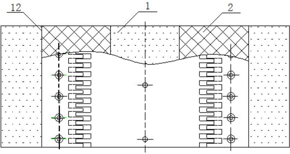
[0028] Such as figure 1 , 2 The sliding type seamless expansion device of the present invention shown includes a top pavement layer 1, an elastomer prefabricated block 2, an asphalt concrete pavement layer 3, a fixed comb plate 4, a fixed bolt 5, a separation cloth 6, and a slide plate 7. Fixing steel nails 8, sponge body 9, intersecting comb tooth plate 10 and adhesive 12, the above components are all arranged on the periphery of the main beam 11.

[0029] Expansion joints are set between the main beams 11, wherein the upper surface of the main beam 11 is provided with a comb-tooth plate, which is embedded on the upper surface of the main beam 11, and the comb-tooth plate includes a cross-slit comb-tooth plate 10 and the fixed comb-tooth plate 4. The comb-tooth plate set on the upper part of the expansion joint is the cross-slit comb-tooth plate 10, and the one connected to the cross-slot comb-tooth plate 10 is the fixed comb-tooth plate 4. The fixed comb-tooth plate 4 is se...


PUM


Abstract

The invention discloses a slipping type seamless telescopic device. A telescopic seam is arranged between main beams, upper surfaces of the main beams are provided with comb plates, and the comb plate arranged at the upper part of the telescopic seam is a trans-seam comb plate, and a fixing comb plate is connected with the trans-seam comb plate; a top paving layer is arranged at the upper part of the trans-seam comb plate, and both sides of the top paving layer are respectively provided with elastomer prefabricating blocks; left and right sides of the elastomer prefabricating blocks are respectively arranged with bituminous concrete paving layers. The slipping type seamless telescopic device and a bridge face paving layer can be formed to be a continuous body, so as to guarantee stable and comfortable driving; the driving noise is small and waterproof performance is good, and the slipping type seamless telescopic device is convenient to clean and remove snow, and other maintaining works; the structural design is more reasonable, and construction is convenient; the comb plates are respectively arranged beneath the paving layer and above the main beam, and can be fixedly moved; and thereby, the problem of empty lower part of the tooth end of the comb plate is effectively solved, and the shortcoming that the traditional seamless telescopic device is easy to crack is overcame.

Description

technical field [0001] The invention relates to a bridge expansion joint structure, in particular to a sliding type elastic body expansion device adapted to bridge expansion and contraction movement. Background technique [0002] As the main component of the bridge structure's driving safety performance, the bridge expansion device is mainly used to meet the needs of the bridge's longitudinal, horizontal, vertical displacement and earthquake incremental displacement caused by temperature difference, wind force, vehicle-mounted and other conditions, and to ensure the bridge structure. It provides a smooth and comfortable bridge (road) surface environment, allowing vehicles to pass through the telescopic device area at the beam end quickly and smoothly. [0003] The comb-toothed telescopic device is currently used relatively frequently in some provinces in China. From the perspective of the use effect, the comb-toothed telescopic device has the following problems: the lower pa...

Claims


Application Information

Patent Timeline
Patent Type & Authority Applications(China)
IPC IPC(8): E01D19/06
CPCE01D19/06
Inventor 张建东满孝卫袁亮刘朵王锋童浩吴建平
Owner JSTI GRP CO LTD
Why Eureka
Try Eureka