
Photoelectric liquid sensor and water pump with same

A fluid sensor and photoelectric technology, which is applied to the components, pump components, machines/engines, etc. of the pumping device for elastic fluids, can solve the problems of difficult maintenance and replacement, loss of water diversion, insufficient sensitivity, etc., and achieves stable chemical properties, Long service life and small diffraction range

Active Publication Date: 2015-08-19
ZHEJIANG SINCONTROL PUMP IND
View PDF7 Cites 3 Cited by
  • Summary
  • Abstract
  • Description
  • Claims
  • Application Information

AI Technical Summary

Problems solved by technology

[0004] The existing water flow switch has the following defects: 1. The action of the magnet requires a certain stroke and time, so it is not sensitive enough; 2. It cannot work in an environment with a magnetic field, because the external magnetic field will cause the water flow switch to malfunction; 3. It requires a large initial kinetic energy to push the magnet to move. If the water flow switch is used in a water pump, the water flow switch cannot operate during the small water flow of the pump; 4. The reed switch is easy to damage, and the water flow switch is located in the pump casing as a whole 5. It cannot be used in the water environment with impurities, and the channel where the magnet slides is easily blocked by impurities, adsorbed and stuck; 6. The electrical performance is poor, and the safety cannot be guaranteed.
[0007] This kind of check valve only has a one-way valve structure on it. When the water pump is working, because of many circumstances, the water pumped up by the water pump contains a lot of impurities. If there are impurities accumulated in the opening and closing position of the valve, it will cause If the entire one-way valve is not closed tightly, the entire one-way valve will not be able to close, and the water in the pump body will flow back from the one-way valve port and damage the impeller and motor.
And the water diversion in the pump body will be lost. If there is no water diversion in the pump body of the self-priming pump, the self-priming pump will lose its self-priming function
The water pump is not working properly
In addition, when the valve port is opened, the check valve is fully open, and there is no cover at the valve port. When the pump is working, some hard impurities, such as small stones, will enter the pump casing through the check valve with the water flow and will hit the motor. The impeller, serious will damage the impeller

Method used


Image

  • Photoelectric liquid sensor and water pump with same
  • Photoelectric liquid sensor and water pump with same
  • Photoelectric liquid sensor and water pump with same

Examples


Embodiment Construction

[0050] The present invention will be further described in detail below in conjunction with the accompanying drawings and embodiments.

[0051] Such as figure 1 Shown is a preferred embodiment of the present invention.

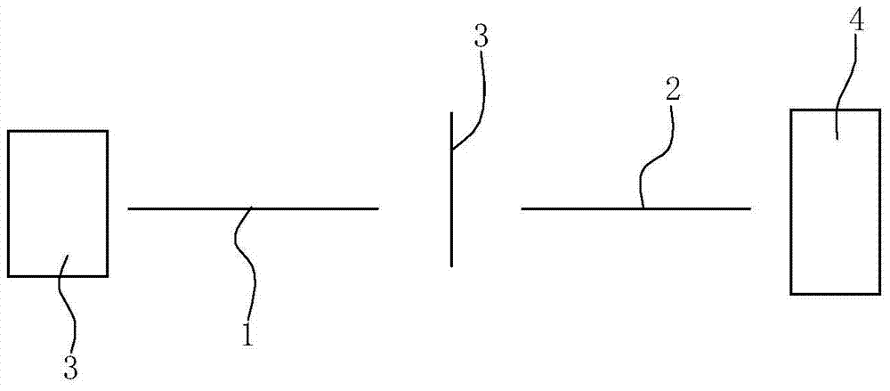
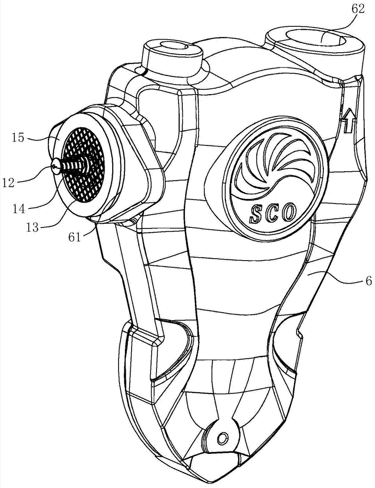
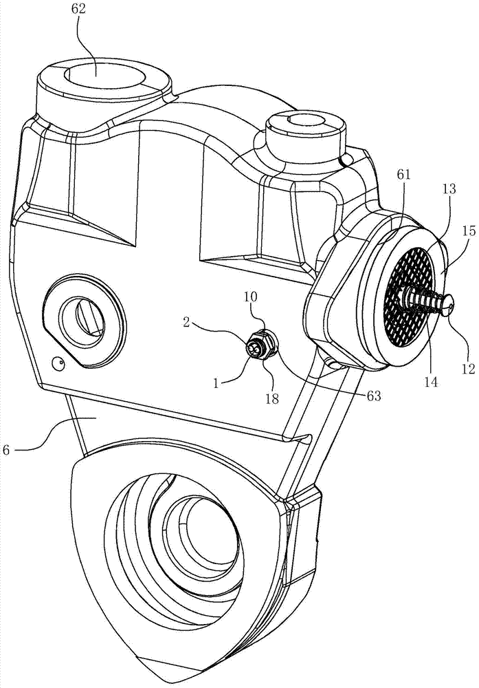
[0052] A photoelectric water flow sensor, including a sending optical fiber 1 and a receiving optical fiber 2 arranged at relative intervals on the left and right, the outer ends of the sending optical fiber 1 and the receiving optical fiber 2 are guided to the water body, and a photoelectric sensor is installed adjacent to the sending fiber 1 outside the water body. The light-emitting diode 3 of the sending fiber 1 is bright, the receiving fiber 2 can receive the light transmitted by the sending fiber 1 and transmit the received light to the photoelectric conversion module 4, and there is a moving part between the sending fiber 1 and the receiving fiber 2 under the action of water flow. The blocking member 5 determines whether it is blocked between the transm...


PUM


Abstract

The invention relates to a photoelectric liquid sensor. The photoelectric liquid sensor is characterized by comprising a transmitting optical fiber and a receiving optical fiber which are bilaterally oppositely arranged at an interval, the outer end of the transmitting optical fiber and the outer end of the receiving optical fiber are led out of a fluid, a light-emitting diode used for lighting the transmitting optical fiber is arranged at the position, adjacent to the transmitting optical fiber, out of the fluid, the receiving optical fiber is capable of receiving the light transmitted by the transmitting optical fiber and transmitting the light to a photoelectric conversion module, a shielding piece capable of moving under the action of the fluid is arranged between the transmitting optical fiber and the receiving optical fiber, and whether the receiving optical fiber can receive the light transmitted from the transmitting optical fiber or not is determined by vertical motion of the shielding piece. The diameter of the transmitted light is quite small due to the features of the light transmitted by the fiber, the light can be sensed if only the shielding piece slightly moves by a distance, and sensitivity is quite high. Compared with a traditional magnetic water flow sensor, the photoelectric liquid sensor has the advantages of freeness from affection of external magnetic field, operation is stable, the fiber is less prone to damage, and the part easy to be damaged is the light-emitting diode which is quite convenient to maintain. The invention further relates to a water pump provided with the above sensor.

Description

technical field [0001] The invention relates to a photoelectric fluid sensor and a water pump with the sensor. Background technique [0002] The water flow switch is a kind of fluid switch. Taking the water flow sensor as an example, it is a sensor device that converts the water flow into an on-off electrical signal after reaching a certain flow rate. It can be used in electric water heaters, solar water heaters, air conditioners and other water systems. Water cycle control, water inlet and outlet control, water heating control, water pump switch control, solenoid valve on-off control or water outlet power off, water outlet power on control and other processes. It is used to detect whether the liquid in the pipeline is flowing and whether the flowing amount (flow rate, that is, the liquid flow pressure) meets the requirements, and at the same time rely on the switch electrical contact to output (provide) the on-off state of a signal. The equipment system judges the working ...

Claims


Application Information

Patent Timeline
IPC IPC(8): F16K37/00F04B53/10
CPCF04B53/1022F04B53/104F16K37/005
Inventor 陈荣国颜正辉陈志平陈海林
Owner ZHEJIANG SINCONTROL PUMP IND
Learn More