
Bias-voltage-control-based adjustable instantaneous frequency measure system

A measurement system and instantaneous frequency technology, applied in the field of microwave photonics, can solve the problem that the trade-off problem has not been well resolved, cannot obtain high precision and large measurement range at the same time, and the actual operation is difficult, etc., to achieve simple operation and stability Good, high application value effect

Inactive Publication Date: 2015-08-19
BEIJING JIAOTONG UNIV
View PDF5 Cites 4 Cited by
  • Summary
  • Abstract
  • Description
  • Claims
  • Application Information

AI Technical Summary

Problems solved by technology

In this type of method, most schemes face a trade-off problem: high precision and large measurement range cannot be obtained at the same time, and only one of the two can be used
But the tradeoffs are not well resolved
Moreover, it is difficult to adjust the polarization angle in actual operation. Therefore, it is necessary to design an instantaneous frequency measurement system with simple bias voltage control and improved accuracy.

Method used


Image

  • Bias-voltage-control-based adjustable instantaneous frequency measure system
  • Bias-voltage-control-based adjustable instantaneous frequency measure system
  • Bias-voltage-control-based adjustable instantaneous frequency measure system

Examples


Embodiment 1

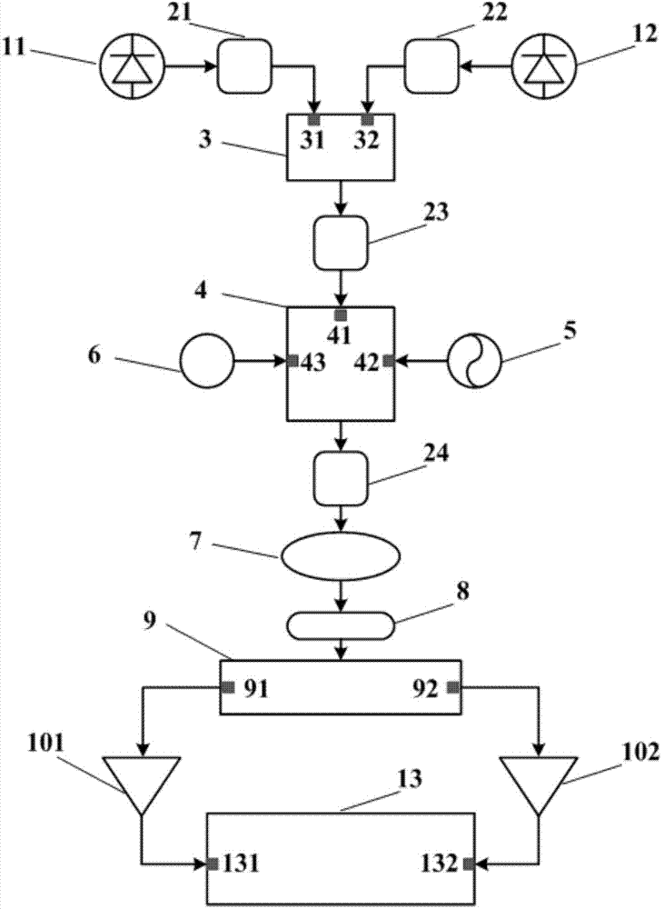
[0040] An adjustable instantaneous frequency measurement system controlled by a bias voltage, such as figure 1 As shown, it is characterized in that: the measurement system includes a first continuous wave laser 11, a second continuous wave laser 12, a first polarization controller 21, a second polarization controller 22, a third polarization controller 23, a fourth polarization Controller 24, polarization beam splitter 3, polarization modulator 4, radio frequency signal source 5, bias voltage source 6, linear polarizer 7, single-mode optical fiber 8, wavelength division multiplexer 9, first photodetector 101, The second photodetector 102, the electrical processing module 13; the specific connection mode is:

[0041] The optical output end of the first continuous wave laser 11 is connected to the optical input end of the first polarization controller 21, the optical output end of the second continuous wave laser 12 is connected to the optical input end of the second polarizat...

Embodiment 2

[0051] An adjustable instantaneous frequency measurement system controlled by a bias voltage, such as figure 1 As shown, it is characterized in that: the measurement system includes a first continuous wave laser 11, a second continuous wave laser 12, a first polarization controller 21, a second polarization controller 22, a third polarization controller 23, a fourth polarization Controller 24, polarization beam splitter 3, polarization modulator 4, radio frequency signal source 5, bias voltage source 6, linear polarizer 7, single-mode optical fiber 8, wavelength division multiplexer 9, first photodetector 101, The second photodetector 102, the electrical processing module 13; the specific connection mode is:

[0052] The optical output end of the first continuous wave laser 11 is connected to the optical input end of the first polarization controller 21, the optical output end of the second continuous wave laser 12 is connected to the optical input end of the second polarizat...

Embodiment 3

[0062] An adjustable instantaneous frequency measurement system controlled by a bias voltage, such as figure 1 As shown, it is characterized in that: the measurement system includes a first continuous wave laser 11, a second continuous wave laser 12, a first polarization controller 21, a second polarization controller 22, a third polarization controller 23, a fourth polarization Controller 24, polarization beam splitter 3, polarization modulator 4, radio frequency signal source 5, bias voltage source 6, linear polarizer 7, single-mode optical fiber 8, wavelength division multiplexer 9, first photodetector 101, The second photodetector 102, the electrical processing module 13; the specific connection mode is:

[0063]The optical output end of the first continuous wave laser 11 is connected to the optical input end of the first polarization controller 21, the optical output end of the second continuous wave laser 12 is connected to the optical input end of the second polarizati...


PUM


Abstract

The invention, which relates to the field of the microwave photonics, provides a bias-voltage-control-based adjustable instantaneous frequency measure system. A first continuous wave laser (11) and a second continuous wave laser (12) are respectively connected with a first polarization controller (21) and a second polarization controller (22); the first polarization controller (21) and the second polarization controller (22) are respectively connected with a polarization beam splitter (3); the polarization beam splitter (3) is connected with a third polarization controller (23); the third polarization controller (23), a radio frequency signal source (5) and a bias voltage source (6) are connected to a light input terminal (41), a radio frequency input terminal (42), and a bias input terminal (43) of a polarization modulator (4); the output of the polarization modulator (4) is connected with a fourth polarization controller (24) connected with a wire grid polarizer (7); and the wire grid polarizer (7) is connected with a single-mode fiber (8) and a wavelength division multiplexing device (9) is used for carrying out shunting. A first photoelectric detector and a second photoelectric detector (101 and 102) respectively detect separated two paths of signals and output the signals to a first input terminal and a second input terminal (131 and 132) of an electric treatment module (13), thereby obtaining an amplitude comparison function.

Description

technical field [0001] The utility model relates to the field of microwave photonics, in particular to an adjustable instantaneous frequency measurement system controlled by a bias voltage. Background technique [0002] Applying microwave photonics, which has important advantages such as large bandwidth, low loss and anti-electromagnetic interference, to the field of instantaneous microwave frequency measurement (IFM, instantaneous frequency measurement), can greatly improve the performance of the instantaneous frequency measurement system. Therefore, based on microwave photonics In recent years, the instantaneous frequency measurement method has attracted more and more attention from domestic and foreign scholars. When designing an instantaneous frequency measurement system, it is often necessary to consider the following factors: 1. It has a large and adjustable measurement range; 2. Improve the measurement accuracy as much as possible; 3. Ensure that the system has strong...

Claims


Application Information

Patent Timeline
Patent Type & Authority Applications(China)
IPC IPC(8): G01R23/12
Inventor 李月琴裴丽李晶郑晶晶王一群翁思俊袁瑾唐宇
Owner BEIJING JIAOTONG UNIV
Learn More