
Circuit board manufacturing method and circuit board with embedded metal matrix

A circuit board manufacturing, metal-based technology, applied in the direction of printed circuit manufacturing, printed circuit, printed circuit connected with non-printed electrical components, etc., to achieve the effect of low cost, good surface smoothness and simple process

Active Publication Date: 2015-08-19
SHENNAN CIRCUITS
View PDF6 Cites 2 Cited by
  • Summary
  • Abstract
  • Description
  • Claims
  • Application Information

AI Technical Summary

Problems solved by technology

[0005] Embodiments of the present invention provide a circuit board manufacturing method and a circuit board embedded with a metal base to solve the above-mentioned various defects caused by the use of local electroplating or local micro-etching processes in the prior art to make local thick copper

Method used


Image

  • Circuit board manufacturing method and circuit board with embedded metal matrix
  • Circuit board manufacturing method and circuit board with embedded metal matrix
  • Circuit board manufacturing method and circuit board with embedded metal matrix

Examples


Embodiment 1

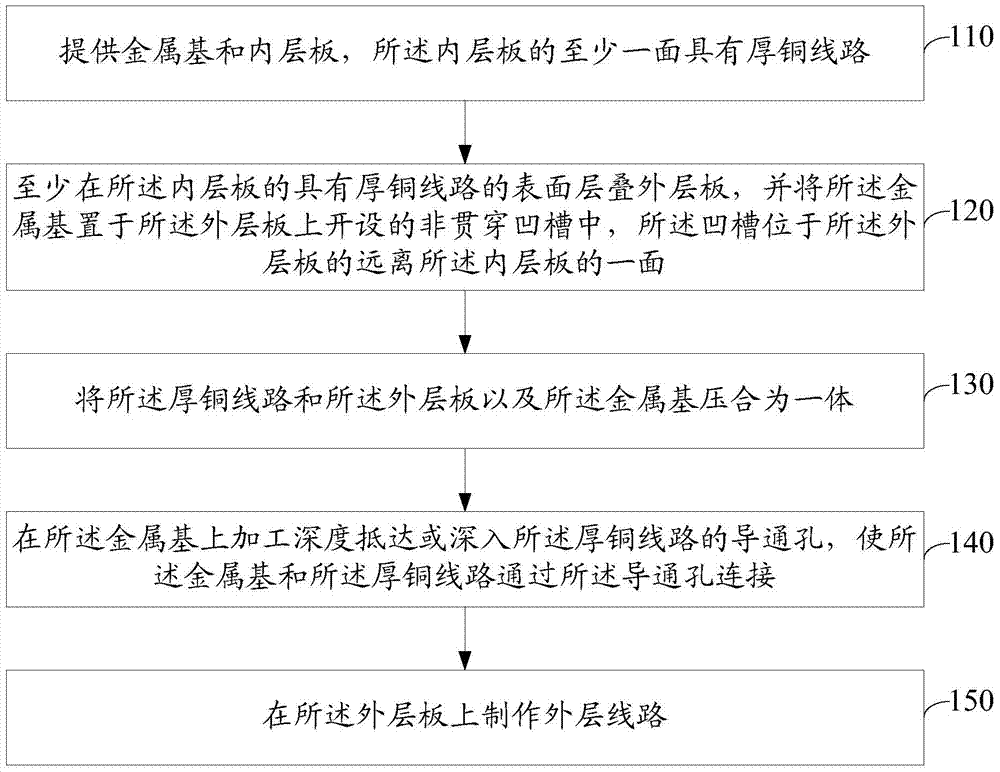
[0026] Please refer to figure 1 , an embodiment of the present invention provides a method for manufacturing a circuit board, which may include:

[0027] 110. Provide a metal base and an inner layer board with thick copper traces on at least one side of the inner layer board.

[0028] In the embodiment of the present invention, the corresponding thickness of the metal base required can be calculated according to the magnitude of the current that needs to be carried by the surface layer of the circuit board, the plane size of the metal base that can be accommodated on the circuit board, and the characteristics of the metal base itself. Then blank the metal plate with the corresponding thickness, and mill the metal base of the corresponding size according to the plane size of the metal base on the surface of the circuit board by milling the shape. And the burrs around the metal base can be removed by grinding. Finally, the metal base can also be browned. The metal base may be...

Embodiment 2

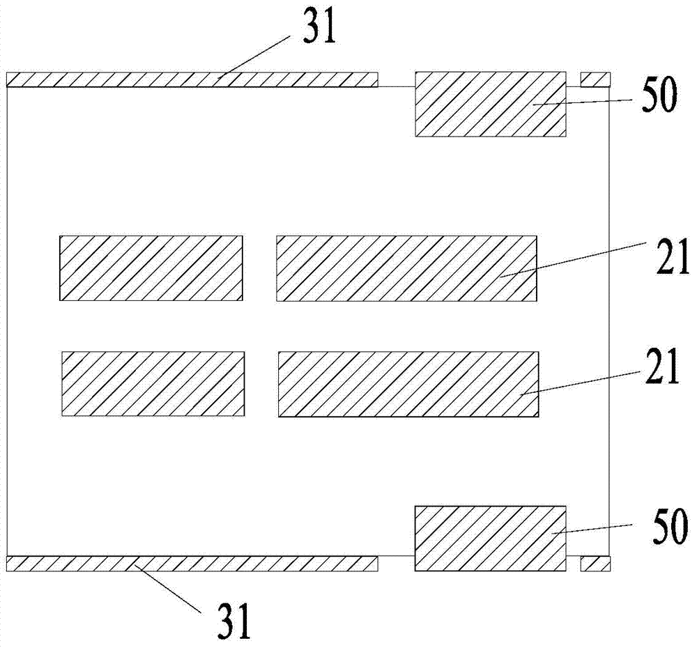
[0044] Please refer to Figure 2d , an embodiment of the present invention provides a circuit board embedded with a metal base, which may include:

[0045] The outer thin copper circuit layer 33, the insulating layer 32, the inner thick copper circuit layer 21 and the metal base 50; the metal base 50 is embedded in the outer thin copper circuit layer 33 but not through the insulating layer 32 In the groove 40; at least one via hole 71 runs through the metal base 50 and reaches or penetrates into the inner thick copper wiring layer 21, and the metal base 50 and the inner thick copper wiring layer 21 pass through the The via hole 71 is connected.

[0046] Optionally, the metal base 50 has a metallized through hole 72 at its boundary.

[0047] Optionally, the outer surface of the metal base 50 and the outer surface of the outer thin copper circuit layer 33 are located on the same plane.

[0048] Such as Figure 2e The point circuit board plan view shown, in some embodiments o...


PUM


Abstract

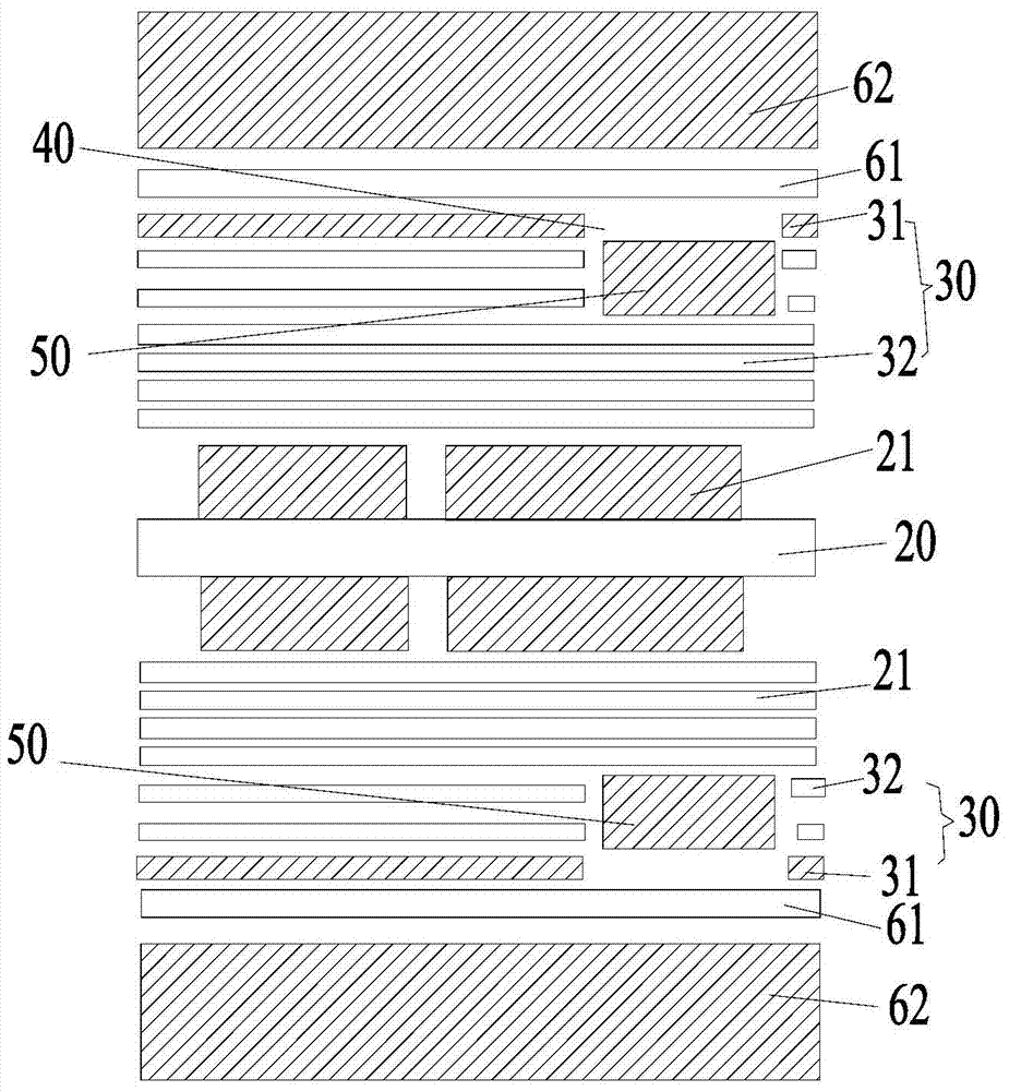
The invention discloses a circuit board manufacturing method and a circuit board with an embedded metal matrix, thereby settling multiple defects caused by manufacture of partial thick copper through partial electroplating or partial micro-corrosion technology in prior art. In some embodiments of the invention, the circuit board manufacturing method comprises the steps of supplying the metal matrix and an inner layer board, wherein at least one surface of the inner layer board is provided with a thick copper line; laminating an outer layer board on the surface with the thick copper line on the inner layer board, placing the metal matrix in a non-through trough which is arranged on the outer layer board, wherein the trough is arranged on the surface which is far from the inner layer board on the outer layer board; pressing the thick copper line, the outer layer board and the metal matrix for integrating; machining at least one conducting hole which arrives at or penetrates deeply into the thick copper line on the metal matrix, so that the metal matrix is connected with the thick copper line through the conducting hole; and manufacturing an outer layer line on the outer layer board.

Description

technical field [0001] The invention relates to the technical field of circuit boards, in particular to a circuit board manufacturing method and a circuit board embedded with a metal base. Background technique [0002] In order to facilitate the input and output of large currents, the circuit boards of power supplies and other products generally use thick copper embedded in the inner layer as the carrier for carrying large currents. If the current needs to be output to a local area on the surface of the circuit board, it is also necessary to make local thick copper on the surface of the circuit board. In the prior art, a local electroplating or local micro-etching process is used to make local thick copper on the surface layer of the circuit board. [0003] However, due to the unevenness of electroplating or micro-etching, the copper thickness of each part of the surface layer of the circuit board treated by the above two processes is very different, and the flatness is ext...

Claims


Application Information

Patent Timeline
Patent Type & Authority Applications(China)
IPC IPC(8): H05K1/18H05K3/00
Inventor 沙雷崔荣刘宝林
Owner SHENNAN CIRCUITS
Learn More