Supercharge Your Innovation With Domain-Expert AI Agents!

Heat-assisted magnetic recording head, semiconductor laser element, and manufacturing method of semiconductor laser element

一种激光元件、半导体的技术,应用在半导体激光器的结构细节、半导体激光器、磁记录头等方向,能够解决半导体激光元件40与浮动块10紧贴性降低、不能充分提升热辅助磁记录头1散热性、发光部52与凹部51体积差较大等问题,达到提升平坦性、防止蚀刻、提升导热性的效果

Active Publication Date: 2018-12-07
SHARP FUKUYAMA LASER CO LTD
View PDF6 Cites 0 Cited by
  • Summary
  • Abstract
  • Description
  • Claims
  • Application Information

AI Technical Summary

Problems solved by technology

This also causes a problem that the adhesion between the semiconductor laser element 40 and the slider 10 is reduced, and the heat dissipation of the heat-assisted magnetic recording head 1 cannot be sufficiently improved.
[0033] In addition, since the volume difference between the light emitting part 52 and the concave part 51 is large, the internal deformation is unevenly formed.
Therefore, there is a problem that the adhesion between the semiconductor laser element 40 and the slider 10 is further reduced, and the stability of laser emission from the semiconductor laser element 40 is degraded.

Method used


Image

  • Heat-assisted magnetic recording head, semiconductor laser element, and manufacturing method of semiconductor laser element
  • Heat-assisted magnetic recording head, semiconductor laser element, and manufacturing method of semiconductor laser element
  • Heat-assisted magnetic recording head, semiconductor laser element, and manufacturing method of semiconductor laser element

Examples


no. 1 Embodiment approach

[0061] Embodiments of the present invention are described below with reference to the drawings. For the convenience of explanation, for the aforementioned Figure 12 , Figure 13 In the conventional examples shown, the same parts are denoted by the same reference numerals. figure 1 A front view showing the heat-assisted magnetic recording head of the first embodiment. The heat-assisted magnetic recording head 1 is mounted on an HDD device or the like, and is disposed on a magnetic disk D so as to be axially movable by being supported by a suspension (not shown).

[0062] The heat-assisted magnetic recording head 1 includes: a slider 10 facing a magnetic disk D; and a semiconductor laser element 40 bonded to the slider 10 with a thermally conductive adhesive 19 . The slider 10 floats on the magnetic disk D rotating in the direction of the arrow A, and has a magnetic recording unit 13 and a magnetic reproducing unit 14 at the end on the medium ejection side. The magnetic rec...

no. 2 Embodiment approach

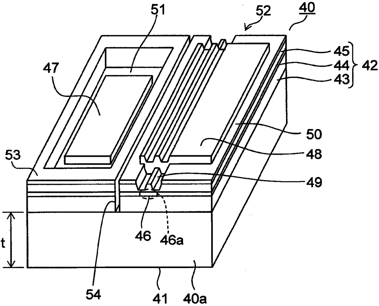
[0102] Next, Figure 10 A perspective view showing a semiconductor laser element 40 of the heat-assisted magnetic recording head 1 according to the second embodiment. For the convenience of explanation, for the aforementioned figure 2 The same parts as those in the first embodiment shown are given the same reference numerals. The shape of the protective wall 53 of the present embodiment is different from that of the first embodiment. Other parts are the same as the first embodiment.

[0103] The protective wall 53 is open in one direction facing the light emitting portion 52 . Even with such a configuration, the same effect as that of the first embodiment can be obtained. At this time, the separation groove 54 is formed so as not to overlap with the first electrode 47 projected on the emission surface 40a. This prevents adhesive 19 (refer to figure 1 ) Attachment to the first electrode 47.

no. 3 Embodiment approach

[0105] Next, Figure 11 A perspective view showing a semiconductor laser element 40 of the heat-assisted magnetic recording head 1 according to the third embodiment. For the convenience of explanation, for the aforementioned figure 2 The same parts as those in the first embodiment shown are given the same reference numerals. The shape of the protective wall 53 of the present embodiment is different from that of the first embodiment. Other parts are the same as the first embodiment.

[0106] The protective wall 53 is divided by the groove part 53a at several positions in the circumferential direction. Even with such a configuration, the same effect as that of the first embodiment can be obtained. At this time, the groove portion 53a on the emission surface 40a is arranged so as not to overlap with the first electrode 47 projected on the emission surface 40a. This prevents adhesive 19 (refer to figure 1 ) Attachment to the first electrode 47. In addition, the groove par...


PUM


Abstract

Positive: substrate (41), which is composed of semiconductor; Everbright (52), which has the substrate (41) as the base. A semiconductor laminate film (42) of a conductive type semiconductor layer (45), and a strip-shaped optical waveguide (46) is formed by the active layer (44); a ring-shaped protective wall (53), which is in phase with the light-emitting portion (52) Adjacent is formed by a semiconductor laminate film (42), and surrounds the recess (51) with the substrate (41) or the first conductivity type semiconductor layer (43) as the bottom surface; the first electrode (47) is arranged in the recess (51) the bottom surface; and a second electrode (48), which is arranged on the upper surface of the light-emitting part.

Description

technical field [0001] The present invention relates to a single-sided double-electrode semiconductor laser element and a heat-assisted magnetic recording head using the same. In addition, the present invention relates to a method of manufacturing a single-sided double-electrode semiconductor laser element. Background technique [0002] Along with the development of the information society in recent years, the high-definition of audio and video has been promoted, and the data communication volume of the Internet has increased remarkably. In addition, the amount of data accumulated on the Internet has greatly expanded due to the development of so-called cloud computing, and it is predicted that this tendency will continue to increase in the future. Under such circumstances, expectations for increasing the capacity of information recording systems that store electronic data are increasing. [0003] As a large-capacity information recording device, a magnetic recording device...

Claims


Application Information

Patent Timeline
Patent Type & Authority Patents(China)
IPC IPC(8): H01S5/02G11B5/02G11B5/31
CPCG11B5/314G11B5/6088G11B2005/0021H01S5/2231H01S5/16H01S5/2004H01S5/209H01S5/34313H01S5/04257H01S5/0236H01S5/02251G11B7/125G11B7/22H01S5/2202H01S5/223H01S5/3211H01S2304/02H01S2304/04
Inventor 川上俊之有吉章
Owner SHARP FUKUYAMA LASER CO LTD
Features
  • R&D
  • Intellectual Property
  • Life Sciences
  • Materials
  • Tech Scout
  • Unparalleled Data Quality
  • Higher Quality Content
  • 60% Fewer Hallucinations
Learn More