Manufacturing method of optical microstructure, machine table and light guide plate of machine table

A technology of optical microstructure and manufacturing method, which is applied in the direction of optics, light guides, optical components, etc., can solve the problems of long processing time, prolonged processing time, and uneven distribution of protrusions, etc., to achieve the best smoothing effect and improve Productivity and the effect of shortening the time required for processing

Inactive Publication Date: 2015-08-26
苏州向隆塑胶有限公司
View PDF8 Cites 8 Cited by
  • Summary
  • Abstract
  • Description
  • Claims
  • Application Information

AI Technical Summary

Problems solved by technology

[0008] However, although the above method can reduce the impact of the protrusions on the overall optical structure pattern, it must undergo secondary laser processing, and the distribution of the protrusions is not fixed, so the second laser beam must also be processed one by one. Adjust the bombardment position a...

Method used


Image

  • Manufacturing method of optical microstructure, machine table and light guide plate of machine table
  • Manufacturing method of optical microstructure, machine table and light guide plate of machine table
  • Manufacturing method of optical microstructure, machine table and light guide plate of machine table

Examples


experiment example 1

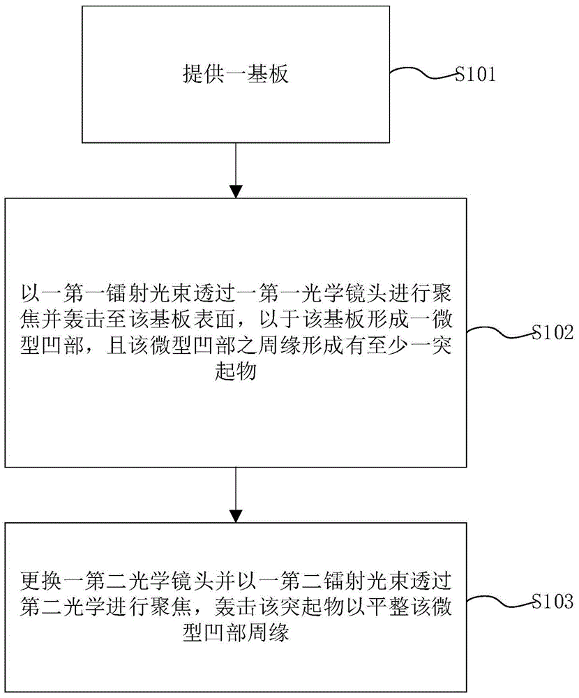
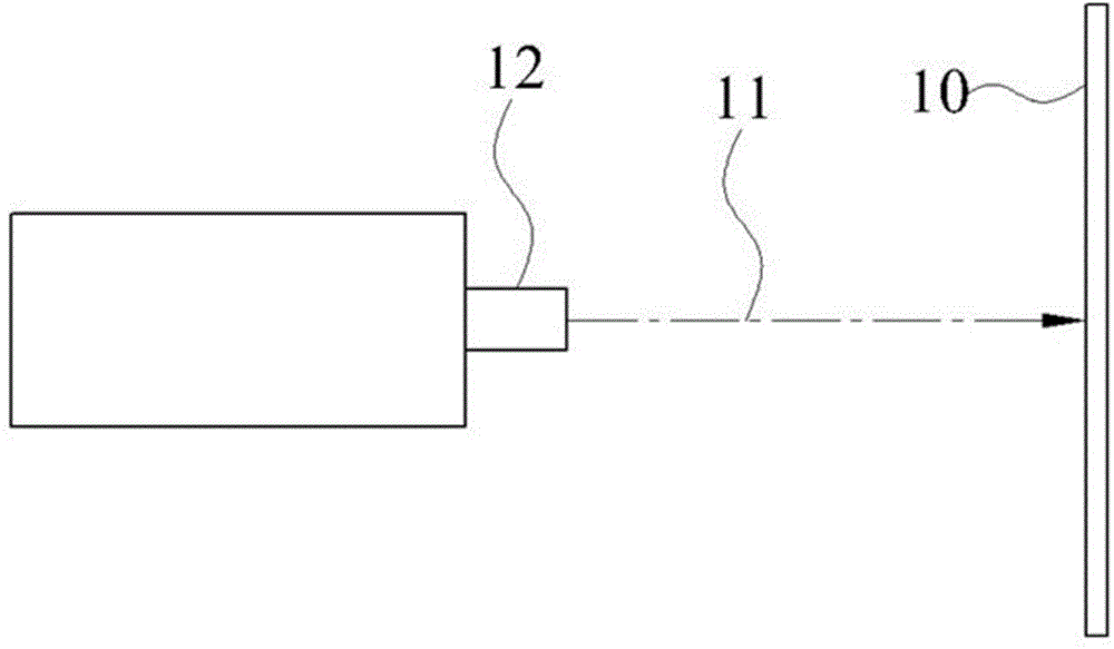
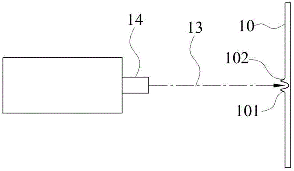
[0074] Please refer to figure 1 and Figure 2A , Figure 2B , which is the method step chart and processing schematic diagram of Experimental Example 1 of the present invention. In view of the deficiencies in the known methods of using lasers to manufacture optical structures for light guide plates, the inventors have carried out many experiments in the field of laser processing to obtain an optimal method for processing optical microstructures through lasers, in order to effectively solve these deficiencies and improve processing efficiency. best way. Experimental Example 1 of the present inventors will be described below.

[0075] Common laser beam output uses electromagnetic waves to pass through the gain medium to adjust the characteristics of the output laser beam. And the gain medium can be sealed in the optical resonant cavity, so as to further make the electromagnetic wave resonate in the optical resonant cavity, so that the electromagnetic wave continuously passes...

experiment example 2

[0079] In view of the shortcomings still in Experimental Example 1, the inventor conceived another processing method, which is as described in Experimental Example 2 below. Please refer to image 3 and Figure 4 , which is a schematic diagram of the method steps and the processing state and micro-holes of Experimental Example 2 of the present invention. A method for manufacturing an optical microstructure is proposed in Experimental Example 2, the steps of which are: step S201, providing a substrate 20; step S202, and irradiating a first laser beam 21 with concentric circular transverse mode images to the substrate 20, A micro recess 201 and a recess 202 are formed on the substrate 20 , and the recess 202 is located around the micro recess 201 .

[0080] Such as Figure 4 As shown, it is the state of the micro-depression 201 and the depression 202 formed on the substrate 20 after the first laser beam bombards the image of the concentric transverse mode. As shown in the fig...

Embodiment 1

[0082] Therefore, after multiple adjustments and experiments, the inventor has further derived the optical microstructure manufacturing method of the multi-mode laser processing machine disclosed by the present invention. Please refer to Figure 5 , 6 , 7A~7C, 8 and Figure 9-10 , which is the method step diagram of Embodiment 1 of the present invention, the schematic diagram of the transverse mode image of the first laser beam, the schematic diagram of the transverse mode image of each second laser beam, the schematic diagram of the transverse mode state after the first laser beam and the second laser beam overlap, and Schematic diagram of each laser processed substrate. The optical microstructure manufacturing method of the multi-mode laser processing machine includes the following steps.

[0083] Step S301 , providing a substrate 30 , wherein the substrate 30 can be a metal mold or a light guide plate.

[0084] Step S302 , irradiating a first laser beam 31 and a second l...


PUM


Abstract

The invention discloses a manufacturing method of an optical microstructure, a machine table and a light guide plate of the machine table. The manufacturing method of the optical microstructure of the multimode laser machining machine table includes the steps that a substrate is provided; a first laser beam and a second laser beam are irradiated to a beam combiner, and the first laser beam and the second laser beam have different laser modes. The multimode laser machine table used for executing and manufactured through the manufacturing method of the optical microstructure of the multimode laser machining machine table comprises a first laser resonant cavity, a second laser resonant cavity, a bearing platform and a machining unit. The light guide plate is provided with a plurality of optical microstructures. According to the multimode laser machining machine table, the method and the light guide plate of the machine table, the first laser beam coincides with the second laser beam through the beam combiner, a micro concave part and a sunken part can be formed in the substrate through one-time machining and irradiating, the time needed for machining is effectively shortened, and therefore the production efficiency is improved, and a better flattening effect can be achieved on the surface of the substrate.

Description

technical field [0001] The present invention relates to the field of laser processing, in particular to a manufacturing method, machine and light guide plate for forming optical microstructures through multi-mode laser processing. Background technique [0002] The light guide plate is a component used in the backlight module to guide light. It transmits the light provided by the light source to the remote side of the light guide plate through the principle of total reflection, and uses several optical structures arranged on it to destroy the total reflection of light. , to guide the light to the light-emitting surface to form a uniform surface light source. [0003] The traditional method used to form the optical structure of the light guide plate is to directly form dots on the light guide plate through the designed optical structure pattern through screen printing. The size of the optical structure is limited, which in turn affects the output quality and light uniformity....

Claims


Application Information

Patent Timeline
IPC IPC(8): B23K26/36B23K26/402G02B6/00
CPCB23K26/36G02B6/0016G02B6/0038G02B6/0065
Inventor 叶钧皓
Owner 苏州向隆塑胶有限公司
Why Eureka
Try Eureka