Hydraulic auxiliary drive system by adopting wheel hub motors

An auxiliary drive and hydraulic wheel technology, applied in the direction of servo motors, servo motor components, fluid pressure actuators, etc., can solve the problems that cannot meet the large flow requirements of wheel hub motors, cannot meet the power requirements, etc., and achieve simple layout and installation Convenience, small structure size, and the effect of improving the working life

Inactive Publication Date: 2015-08-26
JILIN UNIV
View PDF8 Cites 18 Cited by
  • Summary
  • Abstract
  • Description
  • Claims
  • Application Information

AI Technical Summary

Problems solved by technology

[0004] The invention proposes a hydraulic wheel hub motor to solve the problem that the traditional rear-drive vehicle cannot meet the power requirements on the low adhesion coefficient road surface and the steep slope roa

Method used


Image

  • Hydraulic auxiliary drive system by adopting wheel hub motors
  • Hydraulic auxiliary drive system by adopting wheel hub motors
  • Hydraulic auxiliary drive system by adopting wheel hub motors

Examples


Embodiment Construction

[0036] The present invention will be described in detail below in conjunction with the accompanying drawings.

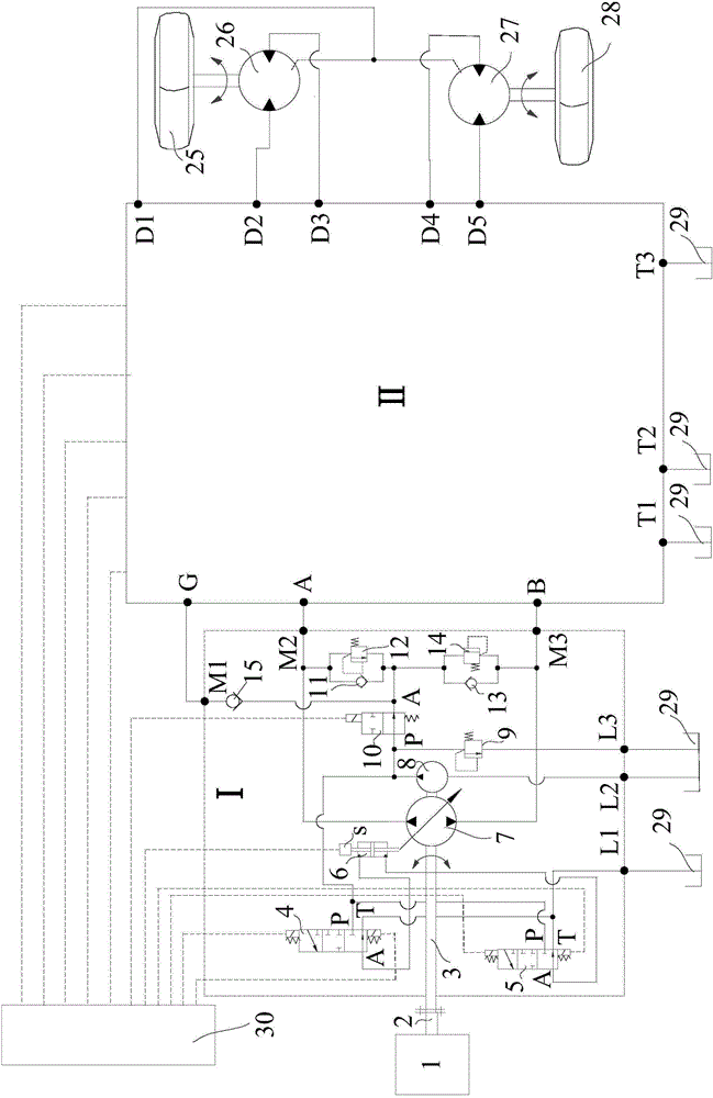
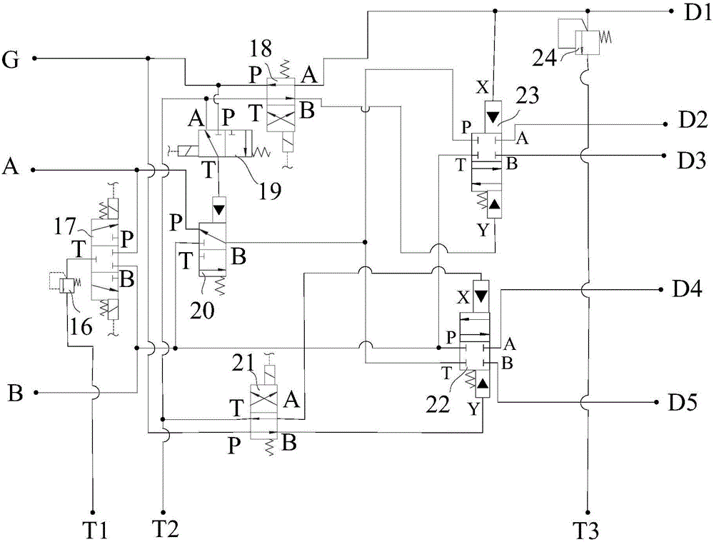
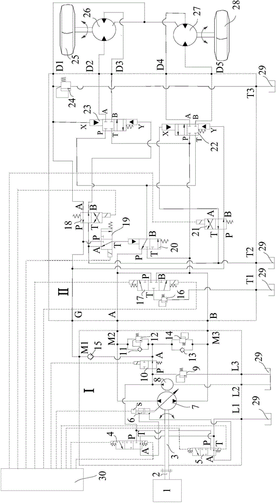
[0037] See attached figure 1 , the hydraulic hub motor auxiliary drive system proposed by the present invention includes a hydraulic pump assembly I, a control valve group II, a controller 30, a power take-off device 1, a power take-off device output shaft 2, a left front wheel 25, a left hub motor 26, a right hub Motor 27, right front wheel 28, oil tank 29.

[0038] See attached figure 1 , the power take-off device 1 and the output shaft 2 of the power take-off device provide power for the hydraulic pump assembly I, and the output shaft 2 of the power take-off device and the input shaft 3 of the hydraulic pump assembly are mechanically connected, and the connection method can be a common key or a spline pair Or connected through a universal joint, the function of the power take-off device 1 and the output shaft 2 of the power take-off device is to transmit power t...


PUM


Abstract

The invention provides a hydraulic auxiliary drive system by adopting wheel hub motors and solves the problems that a traditional rear drive vehicle cannot meet power performance requirements on low-adhesion coefficient road surfaces and large-slope road surfaces, and the existing wheel hub motor hydraulic drive system cannot meet the requirement for high flow of wheel hub motors. The system comprises a hydraulic pump assembly, a control valve bank, a controller, a power take-off device, a power take-off device output shaft, a left front wheel, a left wheel hub motor, a right wheel hub motor, a right front wheel and a fuel tank. Reversing valves in the control valve bank are connected through a pipeline; the reversing valves in the control valve bank are connected with the controller through an electric circuit. According to the invention, a hydraulic pump is driven by the power take-off device, the working positions of the control valve bank are switched by the controller, thus multiple work modes are formed, and control fuel of hydraulically operated reversing valves is controlled by solenoid reversing valves, to control the work states of the wheel hub motors. Reliable work of the system can be guaranteed through the control valve bank, so that the requirement for the high flow of the wheel hub motors is met.

Description

technical field [0001] The invention relates to a hydraulic auxiliary driving system, more precisely, the invention relates to a hydraulic system which adopts a hydraulic wheel hub motor for front wheel auxiliary driving. Background technique [0002] Heavy-duty trucks and engineering vehicles often operate on sandy, muddy, ice-snow and other low-adhesion roads, which require high power performance. In order to improve the dynamic performance of vehicles, traditional heavy vehicles often adopt all-wheel drive, but the system structure is complex and the mass is large. At present, there are proposals for all-wheel drive based on the power system structure of hybrid electric vehicles. For example, the Chinese patent publication number is CN101096180A, and the announcement date is 2008-01-02, which discloses a four-wheel drive hybrid power system, which uses a power distribution system, a front drive axle, a rear drive axle, a generator and an electric motor to realize four-wh...

Claims


Application Information

Patent Timeline
IPC IPC(8): B60K7/00B60K17/28F15B13/02F15B11/08
Inventor 曾小华蒋渊德李相华宋大凤李高志冯涛李胜刘彬娜
Owner JILIN UNIV
Why Eureka
Try Eureka