
Liquefied natural gas vaporization system and automobile

A technology of liquefied natural gas and natural gas, which is applied in the direction of charging system, oil supply device, internal combustion piston engine, etc., which can solve the problems of rising vaporization temperature of vaporized gas, inability to vaporize, and affecting the combustion efficiency of natural gas engine 17, so as to ensure stability , to avoid the effect of too high or too low temperature

Inactive Publication Date: 2015-08-26
BEIQI FOTON MOTOR CO LTD
View PDF5 Cites 0 Cited by
  • Summary
  • Abstract
  • Description
  • Claims
  • Application Information

AI Technical Summary

Problems solved by technology

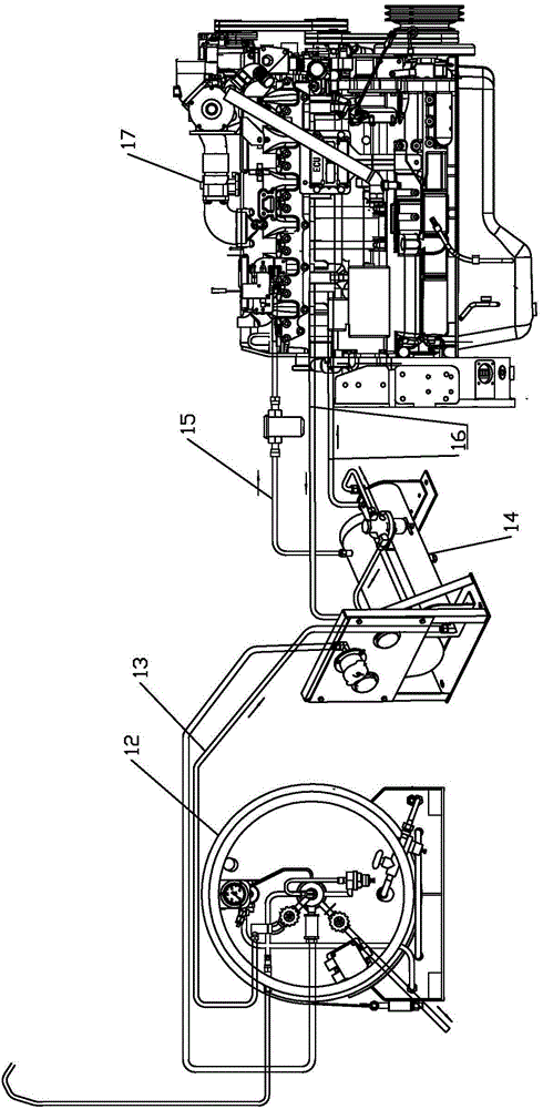
[0004] The natural gas engine 17 requires the temperature of the boil-off gas entering it to be constant, however, in the existing liquefied natural gas vaporization system, the vaporization temperature of the boil-off gas entering the natural gas engine 17 is greatly affected by the ambient temperature
When the ambient temperature is high in summer, the vaporization temperature of the vaporized gas entering the natural gas engine 17 will also increase, the density of the vaporized gas will decrease, and the amount of vaporized gas entering the natural gas engine 17 will decrease for a certain period of time, which will affect the combustion efficiency of the natural gas engine 17
When the ambient temperature is low in winter and the hot water circulation provided by the natural gas engine 17 is not enough to balance the heat energy absorbed during the vaporization of the liquefied natural gas, the vaporization temperature of the vaporized gas entering the natural gas engine 17 will also decrease, and even the problem of inability to vaporize will occur, affecting liquefaction Working with gas equipment

Method used


Image

  • Liquefied natural gas vaporization system and automobile
  • Liquefied natural gas vaporization system and automobile

Examples


Embodiment Construction

[0019] In order to further explain the technical means and effects of the present invention to achieve the intended purpose of the invention, the specific implementation, structure, features and effects of the present invention will be described in detail below in conjunction with the accompanying drawings and preferred embodiments.

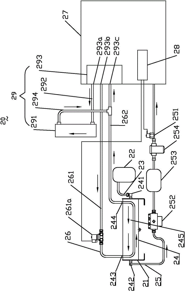
[0020] figure 2 The structure schematic diagram of the liquefied natural gas vaporization system of the present invention is shown. See figure 2 , the liquefied natural gas vaporization system 20 of the present embodiment is used for vaporizing liquefied natural gas to supply the liquefied natural gas engine, which includes a liquefied gas bottle 22, a liquid pipe 23, a vaporizer 24, a gas pipe 25, a heat medium pipe 26, gas equipment 27, electronic control Unit 28 and cooling device 29. The liquefied gas cylinder 22 communicates with the vaporizer 24 through the liquid pipe 23, and the vaporizer 24 communicates with the gas equipment 27. Th...


PUM


Abstract

A liquefied natural gas vaporization system comprises a liquefied gas bottle, a vaporizer, a heating medium pipe and gas burning equipment, wherein the liquefied gas bottle is communicated with the vaporizer, and the heating medium pipe penetrates through the vaporizer which is communicated with the gas burning equipment; the liquefied natural gas vaporization system further comprises an electronic control unit, a temperature sensor electrically connected with the electronic control unit as well as a flow adjusting valve, and the temperature sensor is used for sensing the temperature of liquefied natural gas vaporized gas output by the vaporizer and informs the electronic control unit of the temperature; the flow adjusting valve is arranged on the heating medium pipe, is controlled by the electronic control unit and is used for adjusting flow of heating media in the heating medium pipe. The invention further provides an automobile. The liquefied natural gas vaporization system and the automobile have the advantage that the temperature of the liquefied natural gas vaporized gas output by the vaporizer can be controlled in a certain range.

Description

technical field [0001] The invention relates to the technical field of liquefied natural gas temperature control, in particular to a liquefied natural gas vaporization system and an automobile. Background technique [0002] With the development of new energy technology of liquefied natural gas, the technology of LNG new energy bus (bus using liquefied natural gas as fuel) is changing with each passing day. It has the advantages of small size and long driving range. As a fuel, it is three times that of a passenger car), basically reaching the level of a fuel engine, so that the scope of use of LNG new energy passenger cars has also been expanded, and can be applied to road passenger transportation and tourism markets. The mileage of 1 cubic meter of natural gas at normal temperature and pressure is approximately equal to 1 liter of diesel (gasoline) oil, and the fuel cost of commercial buses using LNG is 33.3% lower than that of diesel. In the case of the same driving range,...

Claims


Application Information

Patent Timeline
IPC IPC(8): F02M21/06
CPCY02T10/30
Inventor 蔡斌周丹宁江清
Owner BEIQI FOTON MOTOR CO LTD
Learn More