
Method for detecting catalyst coking amounts in reactor by utilization of pressure drop

A detection method and pressure drop detection technology, which is applied in the direction of measuring devices, instruments, scientific instruments, etc., can solve the problem that the coking amount of the catalyst cannot be detected on-line in situ, and achieve good economy, wide application range, and reduce equipment investment Effect

Inactive Publication Date: 2015-08-26
JIANGNAN UNIV
View PDF9 Cites 5 Cited by
  • Summary
  • Abstract
  • Description
  • Claims
  • Application Information

AI Technical Summary

Problems solved by technology

[0007] The invention can effectively solve the problem that the in-situ on-line detection of the coking amount of the catalyst in the reactor cannot be realized in the current industrial fluidized bed and fixed bed catalytic reaction process, and proposes an in-situ on-line detection method that can be used for the in-situ on-line detection of the coking amount of the catalyst in the reactor method

Method used


Image

  • Method for detecting catalyst coking amounts in reactor by utilization of pressure drop
  • Method for detecting catalyst coking amounts in reactor by utilization of pressure drop
  • Method for detecting catalyst coking amounts in reactor by utilization of pressure drop

Examples


Embodiment 1

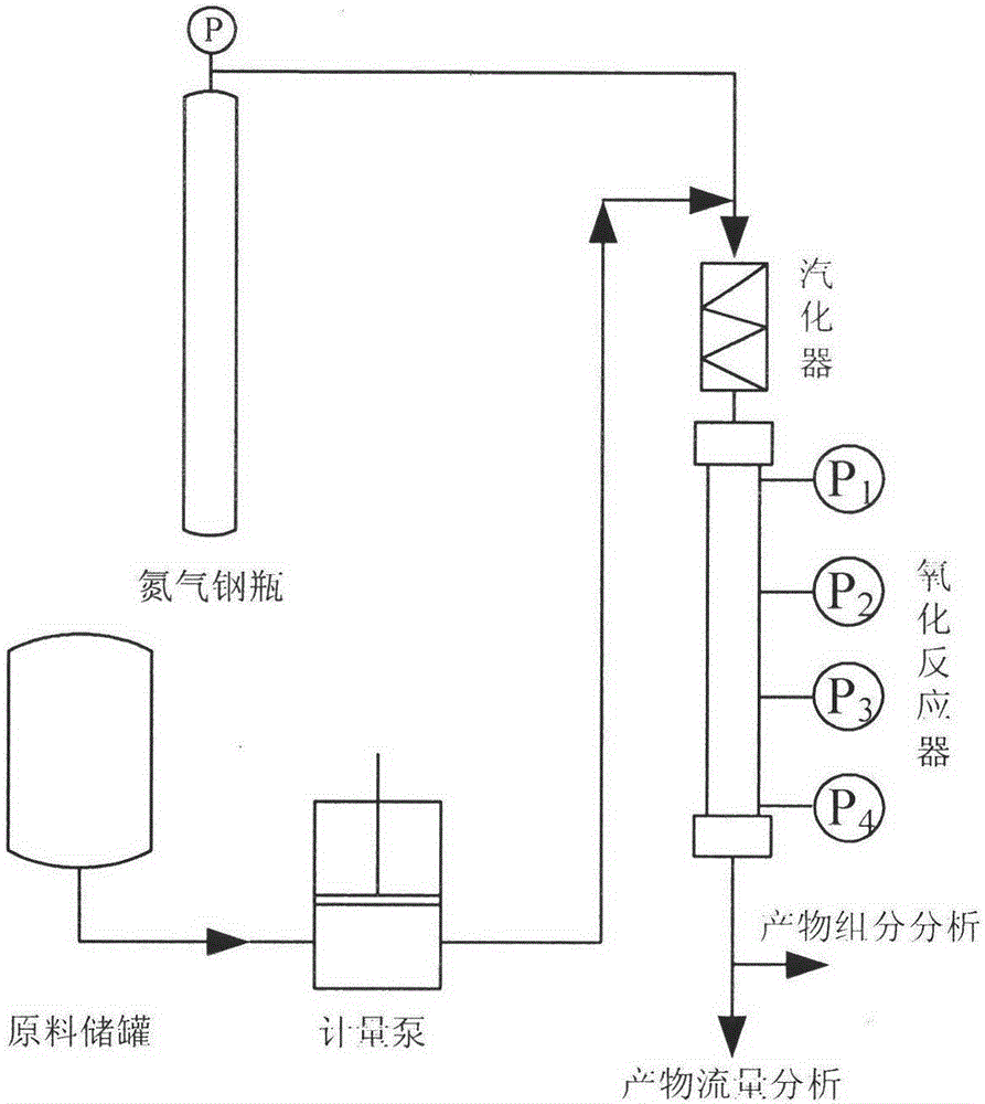
[0028] Embodiment 1: The specific implementation method is illustrated with a laboratory fixed-bed catalyst evaluation device. Such as figure 1 The device shown is a device for laboratory evaluation of the reaction performance of solid catalysts in the process of methanol to olefins. It mainly includes three parts: raw material feeding system, reaction system and product analysis system. The feeding system includes raw material tanks, metering pumps, vaporizers and nitrogen cylinders; the reaction system is mainly composed of fixed-bed reactors, and the reactors are outsourced with electric insulation devices (in figure 1 Not shown in ), to ensure that the catalytic reaction can be carried out at the preset reaction temperature; the product analysis system generally includes product composition analysis and product flow analysis.

[0029] The general fixed-bed catalyst evaluation device only has a pressure gauge installed at the inlet. In order to facilitate the detection of ...

Embodiment 2

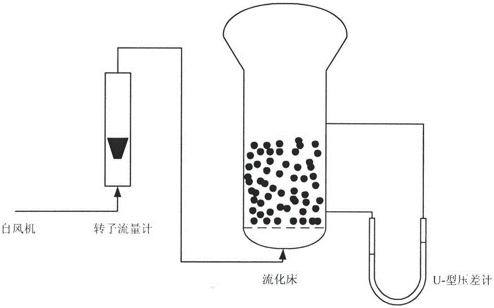
[0038] Embodiment 2: The cold model experiment device that adopts the bed pressure drop to detect the coke content of the solid catalyst in the fluidized bed reactor in the laboratory is as figure 2 shown. The fluidized bed is filled with a catalytic cracking (FCC) catalyst with a known coke content provided by a factory. The gas from the fan enters the fluidized bed after being metered by a gas flow meter. Measured out. The fluidized bed reactor used in the cold model experiment has an inner diameter of 300mm, and the height of the catalyst bed is 600mm during the experiment.

[0039] The coke content of the catalytic cracking catalyst used in the experiment process is known and the coke content is analyzed by a thermogravimetric analyzer, as shown in Table 3.

[0040] Table 3 Real coking amount of FCC catalyst

[0041]

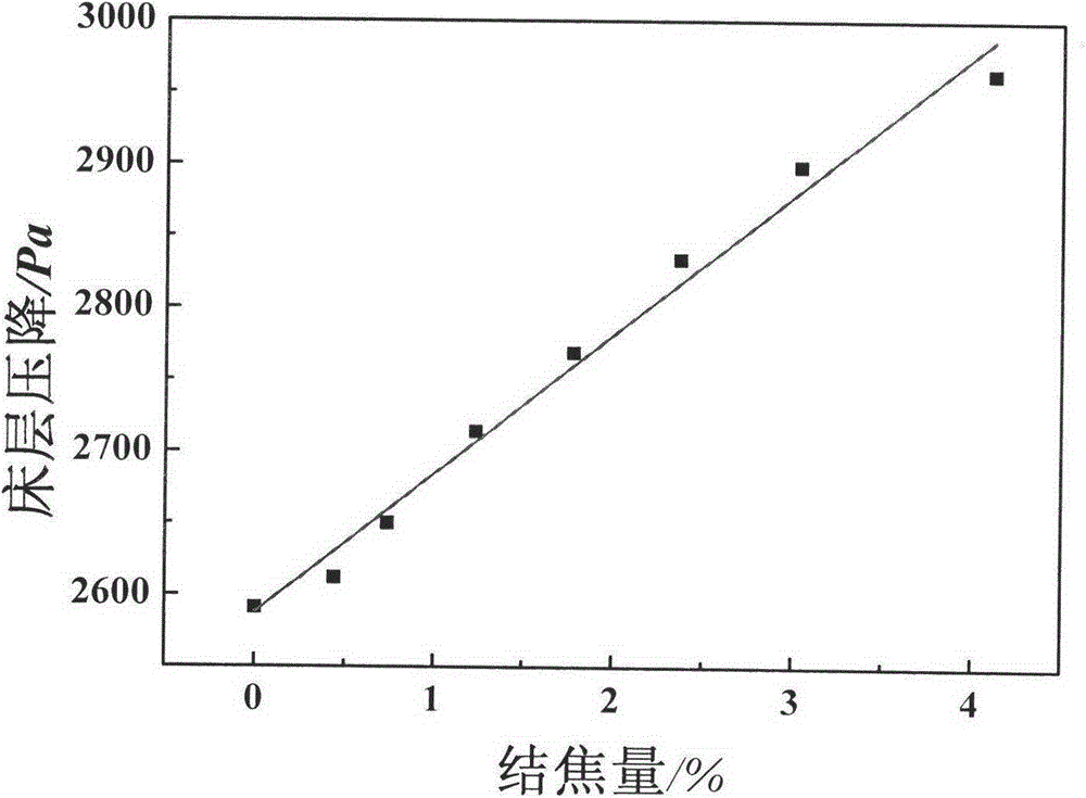
[0042] During the experiment, the U-shaped differential pressure gauge detected the pressure drop of the entire bed, and the measured pressure drop v...


PUM


Abstract

The invention discloses a method for detecting catalyst coke deposit amounts in a reactor by utilization of catalyst bed pressure drop. The method comprises the steps: pressure drop and coke deposit amounts of a catalyst bed layer in a reactor under a plurality of conditions are obtained, the catalyst coke deposit amounts and the pressure drop under the conditions are associated for modeling, and then through prediction model and pressure drop of the catalyst bed layer under a certain condition, the catalyst coke deposit amount in an unknown condition is calculated and obtained. The method is rapid and accurate, has a wide application scope, can be used for on-line detection of catalyst coke deposit amount in a fixed bed or fluidized bed reactor industrially, and has an important meaning for optimization of operation of the catalyst reaction-regeneration process.

Description

technical field [0001] The invention relates to the detection field of catalyst coking amount in a reactor, in particular to a method for detecting catalyst coking amount by using the reactor bed pressure drop. Background technique [0002] During reactions such as methanol to propylene (MTP), methanol to olefins (MTO), catalytic cracking (FCC), natural gas to olefins, and olefin disproportionation, the activity of the catalyst will decrease or disappear due to carbon deposition on the surface or internal pores. The process is called coking of the catalyst. [0003] Catalyst coking is an extremely complex physical and chemical process, and its complexity is reflected in the coke type, coking location and coking mechanism. First of all, according to different conditions such as reaction temperature and time, various cokes are produced, which can be any one of aliphatic hydrocarbons, olefins and aromatic hydrocarbons, or a mixture of these three hydrocarbons. Secondly, durin...

Claims


Application Information

Patent Timeline
IPC IPC(8): G01N5/00
Inventor 吕杭蔚楼旭阳
Owner JIANGNAN UNIV
Features
  • Generate Ideas
  • Intellectual Property
  • Life Sciences
  • Materials
  • Tech Scout
  • Unparalleled Data Quality
  • Higher Quality Content
  • 60% Fewer Hallucinations
Learn More