
A Distributed POS Data Storage Computer System

A computer system and data storage technology, applied in the direction of electrical digital data processing, instruments, etc., can solve the problems of weakened POS data storage computer system flexibility, increased distributed POS system volume and power consumption, increased POS system cost, etc., to achieve Facilitate online fault diagnosis, improve integration and operating speed, and reduce the effect of internal resource occupancy

Inactive Publication Date: 2017-11-10
BEIHANG UNIV
View PDF4 Cites 0 Cited by
  • Summary
  • Abstract
  • Description
  • Claims
  • Application Information

AI Technical Summary

Problems solved by technology

The traditional POS data storage computer system can only receive one channel of POS data at the same time, the maximum speed of receiving data is 115200bps, and the work efficiency is low. To realize the data storage of the distributed POS system, multiple storage computer systems must be used to work at the same time, so It will lead to a sharp increase in the size and power consumption of the distributed POS system. As a key component of the aerial remote sensing system, the size and power consumption of the distributed POS system must be strictly controlled. Therefore, the traditional POS data storage computer system cannot meet the requirements of the distributed POS system. the actual needs of
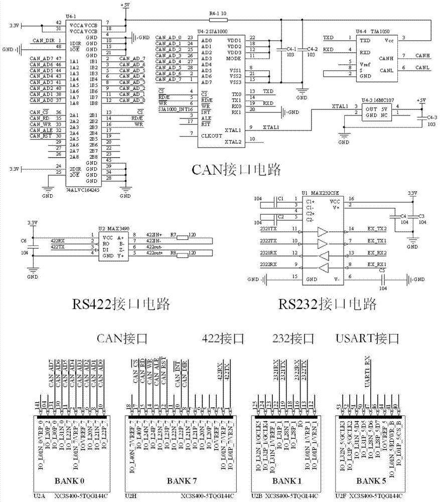
In addition, the traditional POS data storage computer system mostly uses a single communication interface to communicate with the POS system. As long as the communication interface type of the POS system is adjusted according to the task load, the POS storage computer system and the POS system must be connected with an external communication protocol conversion. Circuit modules greatly weaken the flexibility of the POS data storage computer system, and also increase the cost of the entire POS system

Method used


Image

  • A Distributed POS Data Storage Computer System
  • A Distributed POS Data Storage Computer System
  • A Distributed POS Data Storage Computer System

Examples


Embodiment Construction

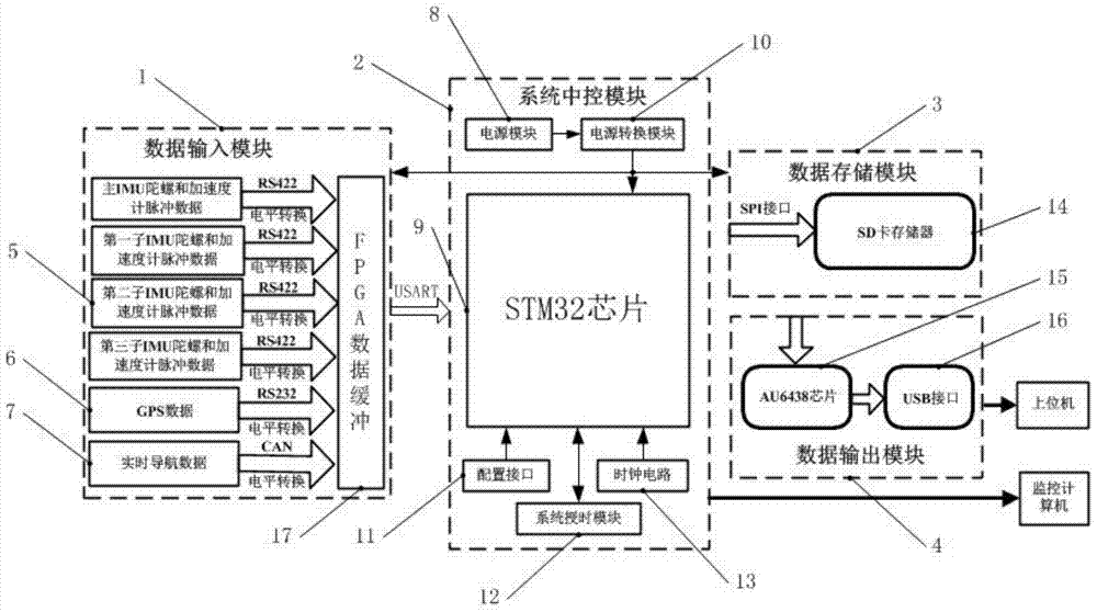
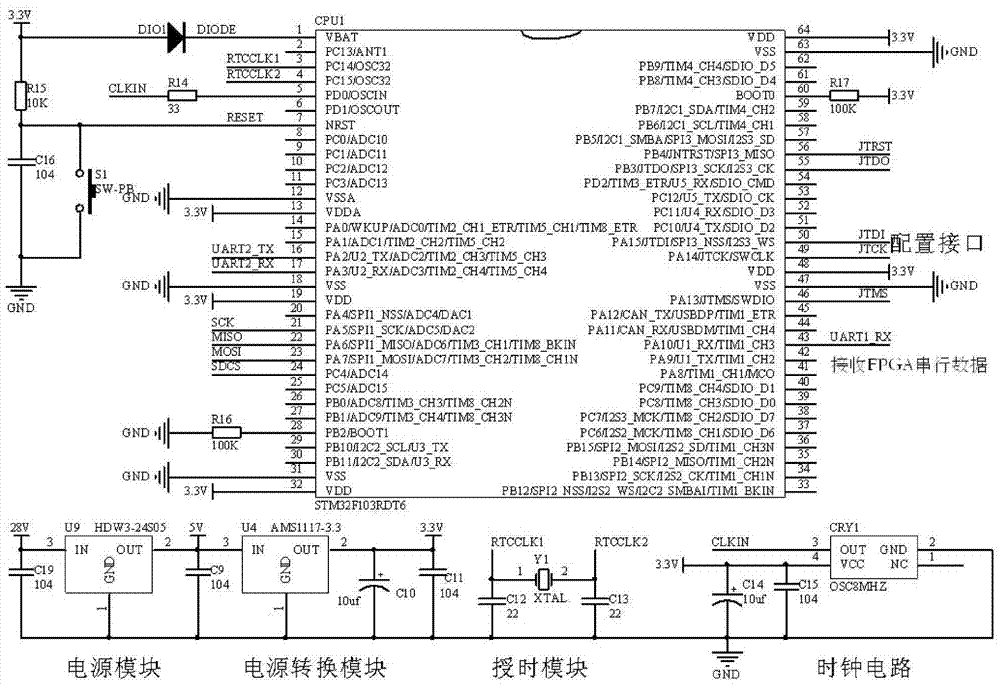
[0020] The specific implementation framework of the technical solution of the present invention is as follows: figure 1As shown, a distributed POS data storage computer system includes four parts: a data input module 1, a system central control module 2, a data storage module 3 and a data output module 4; wherein the data input module 1 utilizes a high-performance FPGA as a hardware buffer , the data input module 1 collects the gyroscope and accelerometer pulse data 5 of the IMU, the GPS data 6 and the real-time navigation data 7 in parallel through the FPGA, repackages the multi-channel POS data collected, and connects to the system central control module 2 through the high-speed USART; The STM32 chip 9 in the system control module 2 receives the data from the data input module 1 through its own USART peripheral, and puts the data into the temporary buffer by using the internal DMA channel of the STM32 chip 9. During the working process of the STM32 chip 9, the clock circuit ...


PUM


Abstract

A data storage computer system for distributed POS uses a high-performance 32-bits ARM microprocessor STM32 as a core controller and comprises a system center control module, a data collecting module, a data storage module and a data output module. The system center control module uses the STM32 as core and is in charge of collaborative operation and integrated scheduling of a whole data storage computer system and carrying out real-time interaction with a supervisory control computer. The data collecting module is used for receiving original data,GPS original data and real time navigation data of a plurality of IMU via FPGA in parallel. The data storage module uses a high-quality high-capacity SD card as a storage medium to finish high-speed stability record of whole system data. The data output module is used for transmitting the data stored in the computer system to an upper computer via a high-speed USB interface to ensure efficient use of the data. The data storage computer system for distributed POS of the invention is applied to a distributed inertial navigation and integrated navigation system.

Description

technical field [0001] The invention relates to a distributed POS data storage computer system, which can be applied to distributed POS (Position and Orientation System, position and attitude measurement system), and can also be applied to inertial navigation, inertial / GPS (Global Position System, global positioning system) ) large-capacity data storage of the integrated navigation system. Background technique [0002] High-precision POS is a key component of the aerial remote sensing system. It provides high-frequency, high-precision time and space reference information for various aerial remote sensing payloads, and improves the imaging accuracy and efficiency of payloads through motion error compensation. With the increasing demand for high-resolution imaging in aerial remote sensing, new high-efficiency multi-task imaging payload joint imaging technology, long-baseline microwave payload interferometry and array technology have gradually become effective means to improve ...

Claims


Application Information

Patent Timeline
Patent Type & Authority Patents(China)
IPC IPC(8): G06F13/20G06F13/28
CPCG06F13/20G06F13/28
Inventor 朱庄生粟昆李驰郭一阳叶文
Owner BEIHANG UNIV
Learn More