
Visible-band multi-wavelength adjustable solid-state Raman laser

A Raman laser and visible light technology, applied in the field of lasers, can solve the problems of high cost and huge system, and achieve the effect of solving the huge system and expanding the adaptability of materials

Active Publication Date: 2015-08-26
BEIJING UNIV OF TECH
View PDF4 Cites 10 Cited by
  • Summary
  • Abstract
  • Description
  • Claims
  • Application Information

AI Technical Summary

Problems solved by technology

It can effectively expand the material adaptability of the above-mentioned system, support the detection, imaging and processing of different samples under different laser wavelengths, and help to solve the problem of a large system with multiple different laser sources under the existing conditions. The problem of high cost lays the foundation for the real realization of the "one machine with multiple functions" of the above system

Method used


Image

  • Visible-band multi-wavelength adjustable solid-state Raman laser
  • Visible-band multi-wavelength adjustable solid-state Raman laser
  • Visible-band multi-wavelength adjustable solid-state Raman laser

Examples


example 1

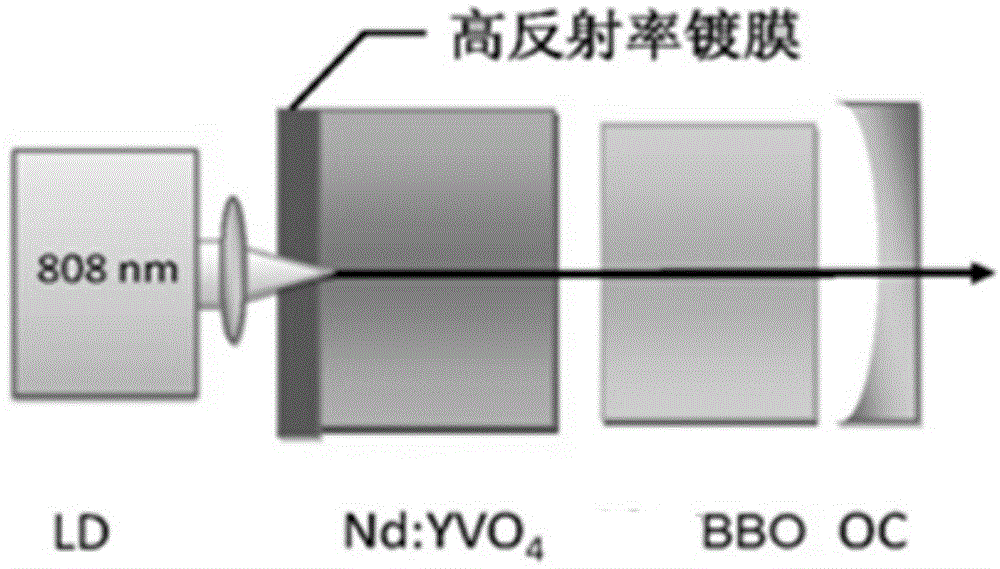
[0060] The pump source LD is an 808nm semiconductor laser diode, the maximum output power is 20W, and the output is linearly polarized light.

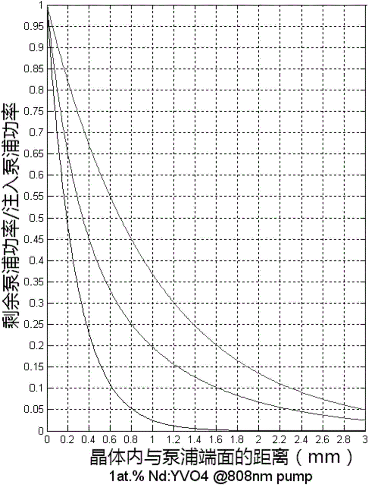
[0061] Choose 1at.% doped Nd:YVO 4 The crystal is a self-Raman crystal, the size is 4mm×4mm (cross section)×3mm (length), and the cutting method is a-axis cutting. The two light-transmitting surfaces of the crystal are coated with an 808nm anti-reflection coating, of which the side facing the pump is coated with a 1000-1500nm high-reflection coating, and the other side is coated with a 1000-1350nm anti-reflection coating to minimize intracavity losses. The polarization direction of the pump light is parallel to the c-axis of the crystal to obtain greater pump absorption. In order to alleviate the thermal lens effect in Nd:YVO4 crystal, Nd:YVO 4 The crystal is placed in a copper heat sink, and the crystal is cooled by a semiconductor refrigeration sheet or a circulating water device, and the temperature is controlled at about 25°C.

...

example 2

[0066] The above Nd:YVO 4 Crystals can also be made of Nd:GdVO 4 ,Nd:LuVO 4 Wait for self-Raman crystals to replace;

[0067]Use 2at.% doped Nd:GdVO 4 The crystal is a self-Raman crystal, the size is 4mm×4mm (cross section)×4mm (length), and the cutting method is a-axis cutting. The two light-transmitting surfaces of the crystal are coated with an 808nm anti-reflection coating, of which the side facing the pump is coated with a 1000-1500nm high-reflection coating, and the other side is coated with a 1000-1350nm anti-reflection coating to minimize intracavity losses. The polarization direction of the pump light is parallel to the c-axis of the crystal to obtain greater pump absorption. To relieve Nd:GdVO 4 thermal lensing in the crystal, but also the Nd:GdVO 4 The crystal is placed in a copper heat sink, and the crystal is cooled by a semiconductor refrigeration sheet or a circulating water device, and the temperature is controlled at about 25°C.

[0068] The BBO crystal...


PUM


Abstract

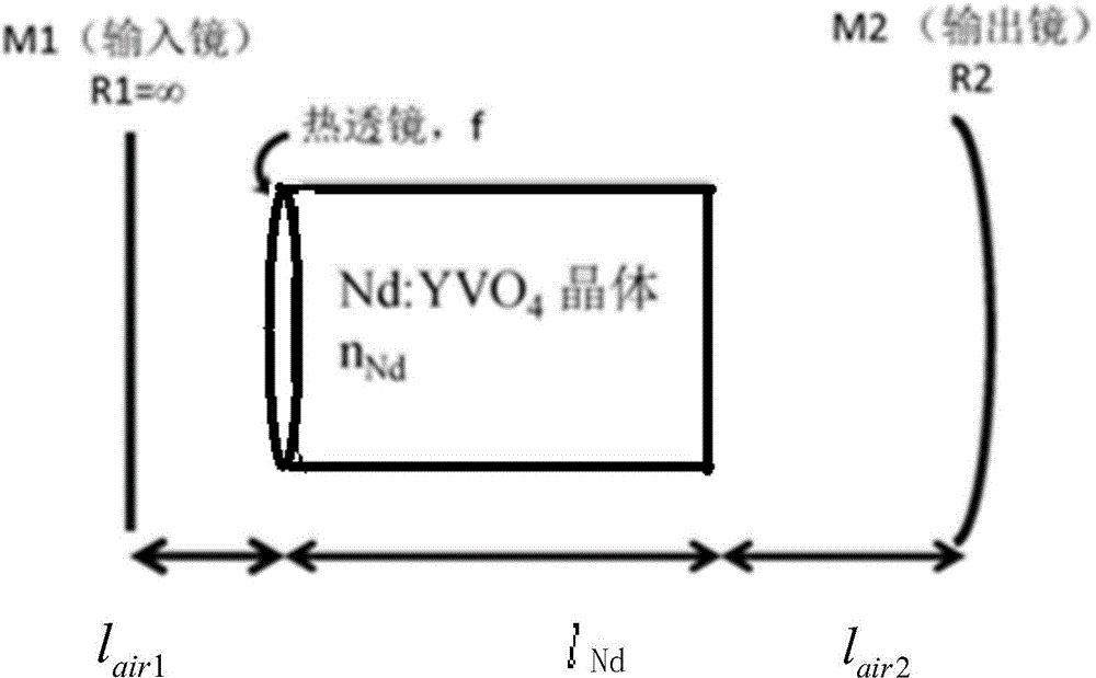
The invention discloses a visible-band multi-wavelength adjustable solid-state Raman laser, which belongs to the field of lasers. The visible-band multi-wavelength adjustable solid-state Raman laser is characterized by sequentially comprising a pumping source LD, a 1-3at.% doped self-Raman crystal, a BBO crystal and a concave mirror OC, wherein a high-reflectivity coating film at the pumping end of the self-Raman crystal and the OC mirror together form a self-Raman resonant cavity, thereby realizing simultaneous lasing of a fundamental frequency light and a cascade Stokes light; through adjusting a phase matching angle of the BBO crystal, intracavity frequency doubling or sum frequency is carried out on a specific wavelength combination selectively, thereby realizing output of different visible wavelengths. Output of multiple visible wavelengths is realized in one laser according to needs, material adaptability for systems such as laser processing, precise measurement and a Raman spectrometer is effectively expanded, problems of large size and high cost caused as one machine drives multiple different laser sources in the prior art can be solved, and a technical foundation is laid for truly realizing one machine with multiple abilities.

Description

technical field [0001] The invention belongs to the field of lasers. Background technique [0002] Stimulated Raman scattering (Stimulated Raman Scattering, SRS) is essentially an inelastic scattering process of light in a medium. After the energy of the incident photons is absorbed by the material atoms, part of the energy is still radiated in the form of photons, while the other part of the energy is stored in the crystal lattice in the form of phonons, and finally converted into heat energy. Therefore, the energy of the radiated photons decreases, the frequency decreases, and the wavelength becomes longer, which is usually called Stokes light. As an important optical frequency conversion method, SRS has been widely used in lasers to obtain new wavelengths that are difficult to achieve in traditional lasers. [0003] Studies have shown that there are a wide variety of solid materials that can achieve the above-mentioned optical conversion with Raman frequency shift chara...

Claims


Application Information

Patent Timeline
Patent Type & Authority Applications(China)
IPC IPC(8): H01S3/30H01S3/108H01S3/16
Inventor 李小丽宋海英刘世炳
Owner BEIJING UNIV OF TECH
Learn More