Eureka AIR delivers breakthrough ideas for toughest innovation challenges, trusted by R&D personnel around the world.

Air distribution system for manufacturing engine heat insulation layer and control method of air distribution system

A technology of air distribution system and control method, applied in the direction of control lamination, chemical instruments and methods, lamination, etc., can solve the problems of profile quality, debonding, wrinkling, etc., to improve the bonding effect and bonding quality And the appearance quality of the profile is improved, and the effect of eliminating local wrinkles

Active Publication Date: 2015-09-02
HUBEI SANJIANG AEROSPACE JIANGHE CHEM TECH
View PDF7 Cites 3 Cited by
  • Summary
  • Abstract
  • Description
  • Claims
  • Application Information

AI Technical Summary

Problems solved by technology

In the patch, it was found that due to the influence of gas generated by operation and residual solvents, it is easy to cause debonding, resulting in interface failure; at the same time, the shape of the rubber airbag also changes freely with the change of air pressure, and the green sheet of the thermal insulation layer changes with the change of air pressure. The change of shape produces radial movement, and the green sheet of the heat insulation layer near the head is displaced axially to varying degrees, causing distortion and wrinkles, and surface quality problems

Method used


Image

  • Air distribution system for manufacturing engine heat insulation layer and control method of air distribution system

Examples


Embodiment 1

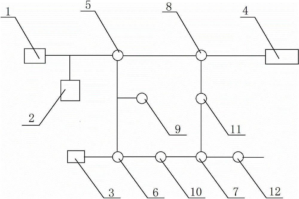
[0021] An air distribution system for the manufacture of engine insulation layer, comprising a first transfer valve 5, a second transfer valve 6, a third transfer valve 7 and a fourth transfer valve 8 connected by pipes in sequence. The connecting valve 8 is connected with the first switching valve 5 to form a circulation channel, wherein the first switching valve 5 is also connected with the vacuum pump 1 and the vacuum chamber 2, the second switching valve 6 is connected with the rubber air bag 3, and the third switching valve 7 An emptying pipeline is also provided, and the fourth transfer valve 8 is also connected to an air compressor 4. A pressure gauge 9 is installed between the first switching valve 5 and the second switching valve 6.

[0022] The specific steps of the control method of the system are:

[0023] 1) Put the heat insulation layer material inside the engine casing, and place the rubber air bag 3 inside the heat insulation layer material, then place the engine i...

Embodiment 2

[0029] An air distribution system for the manufacture of engine insulation layer, comprising a first transfer valve 5, a second transfer valve 6, a third transfer valve 7 and a fourth transfer valve 8 connected by pipes in sequence. The connecting valve 8 is connected with the first switching valve 5 to form a circulation channel, wherein the first switching valve 5 is also connected with the vacuum pump 1 and the vacuum chamber 2, the second switching valve 6 is connected with the rubber air bag 3, and the third switching valve 7 An emptying pipeline is also provided, and the fourth transfer valve 8 is also connected to an air compressor 4. A pressure gauge 9 is installed between the first switching valve 5 and the second switching valve 6. A flow monitor 10 is installed between the second switching valve 6 and the third switching valve 7.

[0030] The specific steps of the control method of the system are:

[0031] 1) Put the heat insulation layer material inside the engine cas...

Embodiment 3

[0037] An air distribution system for the manufacture of engine insulation layer, comprising a first transfer valve 5, a second transfer valve 6, a third transfer valve 7 and a fourth transfer valve 8 connected by pipes in sequence. The connecting valve 8 is connected with the first switching valve 5 to form a circulation channel, wherein the first switching valve 5 is also connected with the vacuum pump 1 and the vacuum chamber 2, the second switching valve 6 is connected with the rubber air bag 3, and the third switching valve 7 An emptying pipeline is also provided, and the fourth transfer valve 8 is also connected to an air compressor 4. A pressure gauge 9 is installed between the first switching valve 5 and the second switching valve 6. A flow monitor 10 is installed between the second switching valve 6 and the third switching valve 7. A first quantitative valve 11 is installed between the third switching valve 7 and the fourth switching valve 8, and a second quantitative...


PUM


Abstract

The invention discloses an air distribution system for manufacturing an engine heat insulation layer and a control method of the air distribution system, and belongs to the technical field of the manufacturing of solid rocket engine heat insulation layers. The air distribution system comprises a first switching valve, a second switching valve, a third switching valve and a fourth switching valve which are sequentially connected by a pipeline, wherein the fourth switching valve is connected with the first switching valve to form a circulation channel; the first switching valve is also connected with a vacuum pump and a vacuum cabin; the second switching valve is connected with a rubber air bag; the third switching valve is also provided with an evacuation pipeline; the fourth switching valve is also connected with an air compressor. The system provided by the invention can eliminate influences of gas generated by pre-stage operation, residual solvents and the like via vacuumization; under the vacuum state, the air bag is pressed to patch so as to prevent gases generated by operation from being brought in; the normal pressure is combined with the air compressor, so that the patching pressure of the rubber air bag is enhanced further, and the pasting effect can be enhanced; the bonding quality and the appearance quality of a mold surface are enhanced obviously.

Description

Technical field [0001] The invention belongs to the technical field of solid rocket motor insulation layer manufacturing, and in particular relates to an air distribution system used for the production of engine insulation layer and a control method thereof. Background technique [0002] At present, the thermal insulation layer of the solid rocket engine adopts the rubber airbag pasting mode, that is, the green sheet of the thermal insulation layer is wrapped on the surface of the rubber airbag, and placed in the corresponding position of the shell together with the rubber airbag, and the rubber airbag is inflated and pressurized to complete the patch. It is found in the patch that due to the influence of the gas generated by the operation and residual solvents, it is easy to cause debonding and cause interface failure; at the same time, the shape of the rubber airbag is also free to change with the change of air pressure, and the green sheet of the insulation layer follows it...

Claims


Application Information

Patent Timeline
Patent Type & Authority Applications(China)
IPC IPC(8): B32B37/10B32B41/00
CPCB32B37/1018B32B41/00
Inventor 朱稼麟陈永钊董晓宏李方朔刘美珍赵碧娟张浩曾庆江宋考生舒梁峻
Owner HUBEI SANJIANG AEROSPACE JIANGHE CHEM TECH
Why Eureka
Eureka Blog
Learn More