
Underground bus rapid transit road system applicable to intersection

An intersection and road system technology, applied in the field of underground bus rapid transit road system, can solve the problems of difficult zero-distance transfer, inconvenient pedestrian boarding, and difficult bus departure, etc. Orderly and efficient, the effect of increasing utilization and efficiency

Active Publication Date: 2015-09-02
HEFEI DESIGN & RES INST LLC OF COAL IND +2
View PDF9 Cites 2 Cited by
  • Summary
  • Abstract
  • Description
  • Claims
  • Application Information

AI Technical Summary

Problems solved by technology

However, there are also some problems in the planning, design and use of the existing BRT system, especially when the island-type BRT bus platform is arranged near the "ten" intersection, it is difficult to be effective due to the limitation of the road width. The condition is close to the intersection, so passengers usually need to walk a long distance when transferring to the BRT bus station bus on the vertical road, and it is very difficult to achieve zero-distance transfer, which brings great inconvenience to people's daily travel ; At the same time, BRT bus stops and dedicated passages take up limited road resources on the road surface, especially near the "ten" intersection with large traffic flow, which is not conducive to keeping the road smooth during the morning and evening rush hours; The road has already occupied a lot of road resources. Due to the limitation of the width of the existing road, it is generally not possible to design the BRT platform to be spacious and comfortable. This will cause traffic congestion during peak hours, and the unfriendly design will make it inconvenient for pedestrians to board the bus; moreover It is difficult to realize the origination of the bus

Method used


Image

  • Underground bus rapid transit road system applicable to intersection
  • Underground bus rapid transit road system applicable to intersection

Examples


Embodiment Construction

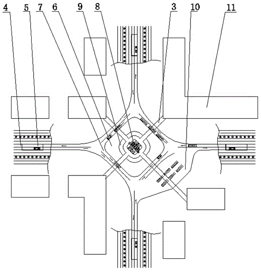
[0024] refer to figure 1 , figure 2 A kind of underground rapid transit road system applicable to intersections shown in the intersection, comprises the above ground layer 1, the basement layer 2 that are positioned at the intersection and the underground pedestrian passageway 3 that communicates with the ground layer 1 and the basement layer 2 respectively, The ground floor 1 is provided with two-way BRT dedicated lanes 4 along the middle of each intersection road, and any BRT dedicated lane 4 communicates with the basement floor 2 through the underpass passage 5, and the center of the basement floor 2 is provided with A diamond-shaped island platform 6, forming an annular passage 7 between the island platform 6 and the periphery of the basement floor 2.

[0025] refer to figure 2 As shown, the basement floor 2 is set between the ground floor 1 and the underground walkway 3, and the center of the island platform 6 is provided with a connection room 8 connected with the un...


PUM


Abstract

The invention relates to an underground bus rapid transit road system applicable to an intersection. The underground bus rapid transit road system comprises an overground floor, an underground floor and an underground pedestrian path, wherein the overground floor and the underground floor are arranged at the intersection and the underground pedestrian path is communicated with the overground floor and the underground floor respectively. Bidirectional bus rapid transit lanes are arranged in the middle of the overground floor along the various intersection lanes, any bus rapid transit lanes are communicated with the underground floor via down-crossing passageways, the center of the underground floor is provided with a rhombic island platform, and an annular passage is formed between the rhombic island platform and the underground floor. The underground bus rapid transit road system sufficiently utilizes overground and underground space resources of the intersection, overcomes the defect that a bus rapid transit stop occupies ground road resource, goes against transfer and is too crowded to let bus depart in the prior art and brings great convenience for bus taking of people in daily life.

Description

technical field [0001] The invention relates to the technical field of municipal construction road facilities, in particular to an underground rapid transit road system used at intersections. Background technique [0002] Bus Rapid Transit (Bus Rapid Transit), referred to as BRT, is a new public passenger transport system between rapid rail transit and conventional buses. It is a medium-capacity transportation mode, and is often called "the subway on the ground". It utilizes modern public transportation technology to cooperate with intelligent transportation and operation management (integrated dispatching system), opens up bus-only roads and builds new bus stations, and realizes the operation service of rail transit mode. It is a unique urban passenger transportation system that reaches the service level of light rail. [0003] Due to the advantages of high efficiency, convenience, and large transportation volume, the BRT system has been widely adopted by many cities. How...

Claims


Application Information

Patent Timeline
Patent Type & Authority Applications(China)
IPC IPC(8): E01C1/04
Inventor 秦强杨利民万杨
Owner HEFEI DESIGN & RES INST LLC OF COAL IND
Learn More