
Testing system and method for seepage field model of tunnel in construction and operation periods

A model test and seepage field technology, applied in the testing of machines/structural components, measuring devices, instruments, etc., can solve problems such as time-consuming, inability to complete the seepage field analysis in the tunnel construction stage, and single effect of simulating the groundwater level.

Active Publication Date: 2015-09-02
SOUTHWEST JIAOTONG UNIV
View PDF8 Cites 13 Cited by
  • Summary
  • Abstract
  • Description
  • Claims
  • Application Information

AI Technical Summary

Problems solved by technology

The test chamber includes a closed pressure-bearing box, a tunnel model composed of circular PVC pipes, and a water storage container. It can study the influence of the drainage type segment lining on the pore water pressure and discharge rate of the surrounding rock, but it cannot reflect the dynamic head and water flow rate. The impact of variable water head, and the grouting layer which has a significant impact on tunnel construction cannot be simulated
[0006] (3) The patentee is Shandong University. Chinese patent application number 201110412569.5 introduces a fluid-solid coupling model test system and its test method for subsea tunnels, including a high-strength rigid test structure frame, a high-strength tempered glass sealed box, a monitoring display system, The computer-controlled platform and pressurized water tank can simulate plane and quasi-triaxial fluid-solid coupling model tests, but it cannot realize the simulation of grouting reinforcement layers and linings with different permeability coefficients, nor can it predict the water inflow and drainage of tunnels under different water heads
[0008] 1. The water head of the above-mentioned model test system is usually constant and cannot be adjusted, and the effect of simulating the groundwater level is single. It is difficult to effectively support the construction of the entire tunnel, and it is impossible to analyze the seepage field of urban tunnels, mountain tunnels and submarine tunnels with different groundwater levels.
[0009] 2. The tunnel construction period is an important stage of tunnel construction. Understanding the changes in the seepage field during the tunnel construction period, predicting the water inflow, testing the water pressure distribution of the surrounding rock-support system and the influence of grouting on the face of the tunnel will affect the smoothness of the tunnel project. Completion is critical and none of the above test systems can complete the seepage field analysis during the tunnel construction phase
[0010] 3. The change of the permeability coefficient and thickness of the surrounding rock grouting reinforcement area around the tunnel has a great impact on the underground seepage field, and will also directly change the water pressure and inrush (drainage) of the tunnel structure. The existing model test devices have not considered or It cannot be adjusted, even if it can be adjusted, it can only be realized by replacing the pre-embedded soil in the box. The operation is cumbersome, causing great interference to the test, and it takes too long, which is not conducive to repeated tests

Method used


Image

  • Testing system and method for seepage field model of tunnel in construction and operation periods
  • Testing system and method for seepage field model of tunnel in construction and operation periods
  • Testing system and method for seepage field model of tunnel in construction and operation periods

Examples


specific Embodiment approach

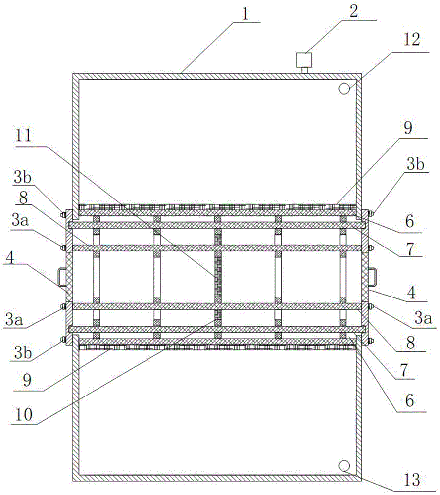
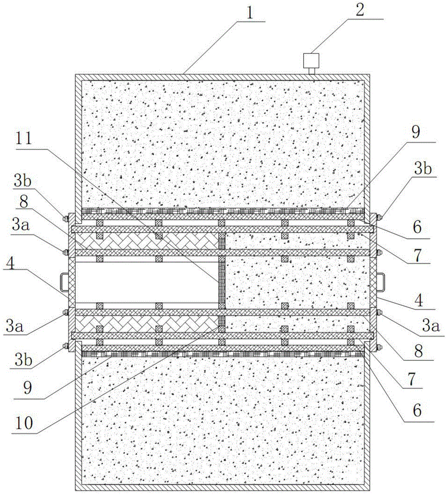
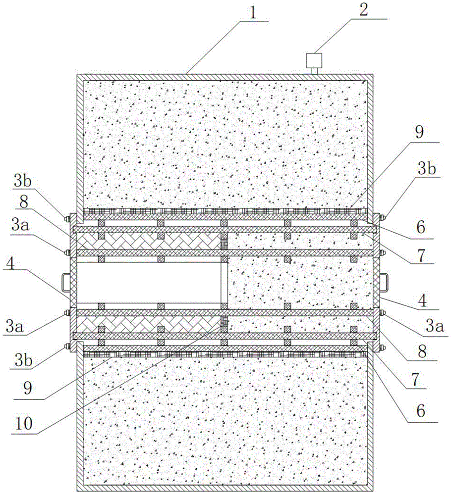
[0042] figure 1 As shown, a specific embodiment of the present invention is: a tunnel seepage field model test system during construction and operation, including a box body 1 of a seepage model box and a data acquisition device for collecting water pressure and seepage flow, and the box body 1 There is a pressure gauge 2 on the top, and an overflow hole 5 for drainage is provided at the bottom of the side wall of the box body 1. Its structural characteristics are:

[0043] The top of the side wall of the box body 1 is provided with an upper water inlet hole 12 of the model box, and the bottom end of the side wall is provided with a lower water inlet hole 13 of the model box; the opposite side walls of the box body 1 are provided with tunnel holes;

[0044] The two ends of the fixed reinforcement cage 6 are welded and fixed on the inner wall of the hole edge of the tunnel hole, the two ends of the outer reinforcement cage 7 and the inner reinforcement cage 8 inside the outer r...


PUM


Abstract

The invention discloses a testing system and method for a seepage field model of a tunnel in construction and operation periods, and the testing system comprises a seepage field model box body and data collection device. The top of the seepage field model box body is provided with a pressure meter, and the bottom of a side wall of the seepage field model box body is provided with an overflowing hole. The top and bottom of a side wall of the seepage field model box body are respectively provided with an upper water inlet of the model box and a lower water inlet of the model box. Two opposite side walls are respectively provided with a tunnel hole. Two ends of each fixed steel reinforcement cage are fixed on inner walls of the edges of the tunnel holes, and the fixed steel reinforcement cages are respectively wrapped by a soil isolating layer. Peripheral bolts of flange plates are fixed on outer walls of edges of the tunnel holes, and the internal and external steel reinforcement cages are fixed between the two tunnel holes through the flange plates. Inner holes of the flange plates are provided with cover plates. A construction-period soil isolating plate is connected between the internal and external steel reinforcement cages in a threaded manner. A tunnel face water-blocking plate is fixed in the internal steel reinforcement cage in a threaded manner. Moreover, the construction-period soil isolating plate and the tunnel face water-blocking plate are located on the same vertical section. The system can test the conditions of the seepage field of the tunnel conveniently, accurately and truly in the construction and operation periods under the action of the seepage field.

Description

technical field [0001] The invention relates to a tunnel seepage field model test system and a test method thereof during construction and operation periods, and belongs to the field of civil engineering tests. Background technique [0002] Long-term leakage of water in the tunnel may lead to a large loss of groundwater outside the tunnel, a drop in the groundwater level, and depletion of surface water sources, accompanied by soil erosion, vegetation destruction, and ground subsidence. Landslides will accelerate the corrosion of anchor rods and arches, and at the same time erode the ancillary facilities in the tunnel. In addition, the accumulated water on the road will also deteriorate the driving environment, affect driving safety, and damage the quality of the road surface. It can be seen that solving the problem of tunnel water leakage will help ensure the safety of the tunnel structure, prolong its service life, and protect the surrounding ecological environment. The cor...

Claims


Application Information

Patent Timeline
Patent Type & Authority Applications(China)
IPC IPC(8): G01M99/00
Inventor 何川李铮骆耀文高翔汪波邹育麟
Owner SOUTHWEST JIAOTONG UNIV
Learn More