Semiconductor laser tube core sintering clamp and sintering method thereof

A laser and semiconductor technology, applied in the direction of semiconductor lasers, lasers, laser parts, etc., can solve the problems of difficult processing and assembly of precision parts, easy deformation of parts, unusable fixtures, etc., to reduce sintering voids, high production efficiency, Easy to use effect

Inactive Publication Date: 2015-09-02
Shandong Huaguang Optoelectronics Co. Ltd.
View PDF5 Cites 2 Cited by
  • Summary
  • Abstract
  • Description
  • Claims
  • Application Information

AI Technical Summary

Problems solved by technology

The disadvantage of this method is that only one laser can be sintered at a time, which is not suitable for batch sintering; and there are many parts in the whole device, it is difficult to process and assemble the precision parts required, and the manufacturing cost is high
The disadvan

Method used


Image

  • Semiconductor laser tube core sintering clamp and sintering method thereof
  • Semiconductor laser tube core sintering clamp and sintering method thereof

Examples


Embodiment Construction

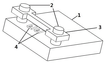
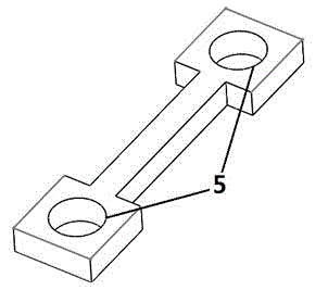
[0020] Such as figure 1 As shown, the semiconductor laser die sintering jig of the present invention includes a base 1 , a fixing column 2 and a pressing block 3 . The base 1 can be a cuboid, a cube, a cylinder or other shapes, preferably a cuboid. The fixed column 2 is fixed on the base 1 by screw connection or welding, and there is at least one set of fixed columns on the base 1, each group is two fixed columns, and 2-20 can be placed within the distance between the two fixed columns Laser die and heat sink 4 (Use an adsorption machine under a microscope to place the semiconductor laser die on the heat sink with solder to form the laser die and heat sink 4, the heat sink refers to the packaging and cooling of the laser die used heat sink), it is advisable to place 2-5 laser dies and heat sinks, so that batch sintering can be performed. A briquetting block 3 is arranged on the two fixed columns of each group. Such as figure 2 , The pressing block 3 is provided with two g...


PUM


Abstract

The invention discloses a semiconductor laser tube core sintering clamp and a sintering method thereof. The clamp comprises a base, fixation columns and a pressure block. The fixation columns are fixed on the base, the base is at least provided with a group of fixation columns, each group comprises two fixation columns, the two fixation columns of each group are provided with the pressure block, and the pressure block is provided with two guide holes and are sleeved on the fixation columns through the two guide holes. The sintering method comprises the following steps: (1), arranging laser tube cores and heat sinks on the two fixation columns of each group of the fixation columns; (2), placing the pressure block on the two fixation columns of each group, enabling the pressure block to apply pressure on the tube cores, and enabling the pressure block to be compacted right opposite to laser tube cores; and (3), carrying out sintering. The semiconductor laser tube core sintering clamp is simple in structure, low in cost and simple to operate, can be conveniently placed in a nitrogen protective cover casing, effectively prevents a solder from oxidation in high-temperature sintering, can realize rapid batch sintering of the tube cores and the heat sinks of semiconductor lasers, and is high in production efficiency.

Description

technical field [0001] The invention relates to a sintering method and a fixture for semiconductor laser tube cores, belonging to the technical field of semiconductor laser tube core sintering. Background technique [0002] With the advancement of science and technology and the development of society, the application of lasers in various fields has gradually expanded. In particular, emerging semiconductor lasers have the advantages of small size, light weight, high electro-optical conversion efficiency, long life and high reliability, and have gradually replaced the traditional gas and solid-state lasers in the application market, and are widely used in industrial processing, medical treatment, and display. , entertainment, communications and security and other fields. Due to the small size and high power characteristic of the semiconductor laser tube core, it is not conducive to the heat dissipation of the tube core. The waste heat generated by the tube core needs to be...

Claims


Application Information

Patent Timeline
IPC IPC(8): H01S5/024H01S5/022
Inventor 杨扬孙素娟李沛旭徐现刚
Owner Shandong Huaguang Optoelectronics Co. Ltd.
Why Eureka
Try Eureka