Large gear grinding machine grinding wheel rack rotation device and rotation control method thereof

A technology of slewing device and grinding wheel frame, which is applied in the direction of gear tooth manufacturing device, gear cutting machine, belt/chain/gear, etc. It can solve the problem of difficult to achieve high-precision, high-sensitivity control, reduced support performance of grinding wheel frame, and difficulty in meeting high rigidity requirements and other problems to achieve the effect of stable rotation, small Abbe error, and improved support rigidity

Active Publication Date: 2015-09-09
秦川机床工具集团股份公司
View PDF7 Cites 4 Cited by
  • Summary
  • Abstract
  • Description
  • Claims
  • Application Information

AI Technical Summary

Problems solved by technology

When the torque motor is in a static state, the output torque drops rapidly. During the grinding process, the grinding wheel frame is stationary, and the support performance of the torque motor to the grinding wheel frame is reduced.
In addition, the overhang of the rotary base is long, the table bearing is installed at the front end of the rotary base, the load on the grinding wheel frame directly acts on the front end of the rotary base through the table bearing, and the support of the rotary base is located at the rear end, so that the rotary base can bear a large bending torque , affecting the grinding accuracy
[0006] For a large gear grinding machine, the load of the grinding wheel frame is large, and it is difficult to meet the high rigidity requirements by relying on a turntable bearing to support the rotation
The circular grating is installed on the rear end of the rotary seat through an intermediate shaft, which is far away from the control target. Due to installation errors and the deflection of the intermediate shaft, the accuracy is poor, and it is difficult to achieve high-precision and high-sensitivity control

Method used


Image

  • Large gear grinding machine grinding wheel rack rotation device and rotation control method thereof
  • Large gear grinding machine grinding wheel rack rotation device and rotation control method thereof
  • Large gear grinding machine grinding wheel rack rotation device and rotation control method thereof

Examples


Embodiment

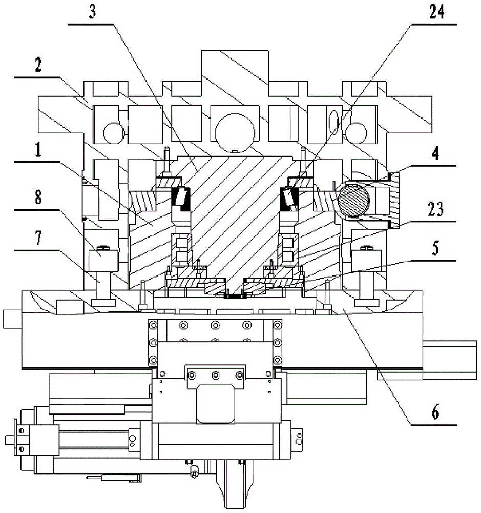
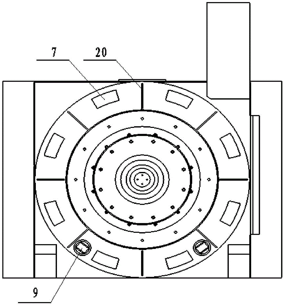
[0041] Such as figure 1 As shown, a grinding wheel frame rotary device for a large gear grinding machine includes a rotary cylinder 1, a rotary seat 2, a main shaft 3, a double-lead anti-backlash worm gear pair 4, a circular grating 5, a grinding wheel frame 6, a clamping mechanism 8 and an unloading mechanism. Dutch agency 9. The main shaft 3 is fastened to the slew seat 2 with bolts (rigid connection). Rotary cylinder 1 is supported on the main shaft 3 through double-row cylindrical roller bearings 23 and tapered roller bearings 24. The grinding wheel frame 6 is directly connected to the rotary drum 1. The rotary drum 1 is driven by the double-lead anti-backlash worm gear pair 4 to realize the grinding wheel frame. Rotation, the rotation position is controlled by the circular grating 5, and can be firmly locked on the rotary base 2 by the clamping mechanism 8. The grinding wheel frame 6 is directly supported by the main shaft 3, which has high rigidity; the main shaft is f...


PUM


Abstract

The invention provides a large gear grinding machine grinding wheel rack rotation device and a rotation control method thereof. The device comprises a rotation cylinder, a rotation seat, a spindle, a dual-lead clearance elimination worm gear, a circular grating, a grinding wheel rack, a clamping mechanism and an unloading mechanism. the spindle and the rotation seat are fixed firmly through bolts, the rotation cylinder is supported on the spindle through a group of rolling bearings, the grinding wheel frame is directly connected with the rotation cylinder and is rotated by the driving of the dual-lead clearance elimination worm gear, the rotation position is controlled by the circular grating, and the grinding wheel rack can be locked on the rotation seat through the clamping mechanism. By means of the device and the method, the requirements for high rigid support, stable and flexible moving and accurate location of large gear grinding machine grinding wheel racks can be met.

Description

technical field [0001] The invention belongs to the field of numerical control machine tools, and in particular relates to a large-scale gear grinding machine grinding wheel frame rotation device and a rotation control method thereof. Background technique [0002] Grinding spindles, dressing devices and other accessories are installed on the grinding wheel frame of the gear grinding machine, and the load is asymmetrical and in a biased state. When grinding helical gears, the grinding wheel frame needs to rotate at a certain angle so that the grinding cutting direction of the grinding wheel is compatible with the helix angle of the tooth groove, which intensifies the asymmetry of the load, especially when grinding large gears. Deep and large, the diameter of the formed grinding wheel used is 500 mm, the thickness is 130 mm, and the grinding load is large. To overcome the load torque and grinding torque caused by the overweight, the support mechanism of the grinding wheel fra...

Claims


Application Information

Patent Timeline
Patent Type & Authority Applications(China)
IPC IPC(8): B23F9/02B23F23/00B23F23/12
Inventor 郭召樊利军
Owner 秦川机床工具集团股份公司
Why Eureka
Try Eureka