Thermoelectric power generation device using flue gas waste heat of rear smoke channel of boiler and semiconductor power generation device

A thermoelectric power generation, tail flue technology, applied in lighting and heating equipment, generators/motors, furnaces, etc., can solve the problem of high cost of raw materials, transportation and maintenance, low heat transfer coefficient of low-pressure economizers, and high quality of work. and other problems, to achieve the effect of improving energy utilization efficiency, increasing the scope of application, and small heat transfer coefficient

Active Publication Date: 2015-09-09
NORTH CHINA UNIV OF WATER RESOURCES & ELECTRIC POWER
View PDF5 Cites 3 Cited by
  • Summary
  • Abstract
  • Description
  • Claims
  • Application Information

AI Technical Summary

Problems solved by technology

[0004] The existing flue gas waste heat utilization device is mainly a low-pressure economizer, but because the temperature of the flue gas is too low and the heat transfer coefficient of the low-pressure economizer is small, a large heat transfer area is required, resulting in a bulky device and metal more consumables
[0005] The main technology for the utilization of flue gas waste heat is the organic Rankine cycle, but the labor required is relatively large, and most of them are organic, which makes the cost of raw materials, transportation and maintenance relatively high

Method used


Image

  • Thermoelectric power generation device using flue gas waste heat of rear smoke channel of boiler and semiconductor power generation device
  • Thermoelectric power generation device using flue gas waste heat of rear smoke channel of boiler and semiconductor power generation device
  • Thermoelectric power generation device using flue gas waste heat of rear smoke channel of boiler and semiconductor power generation device

Examples


Embodiment Construction

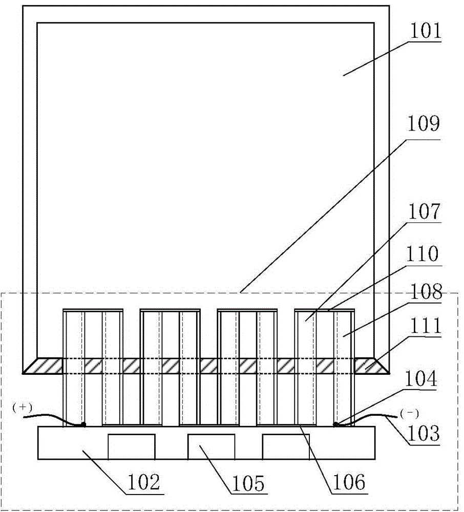
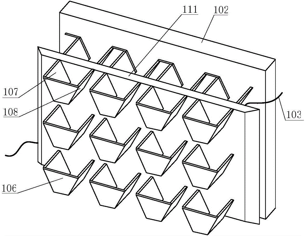
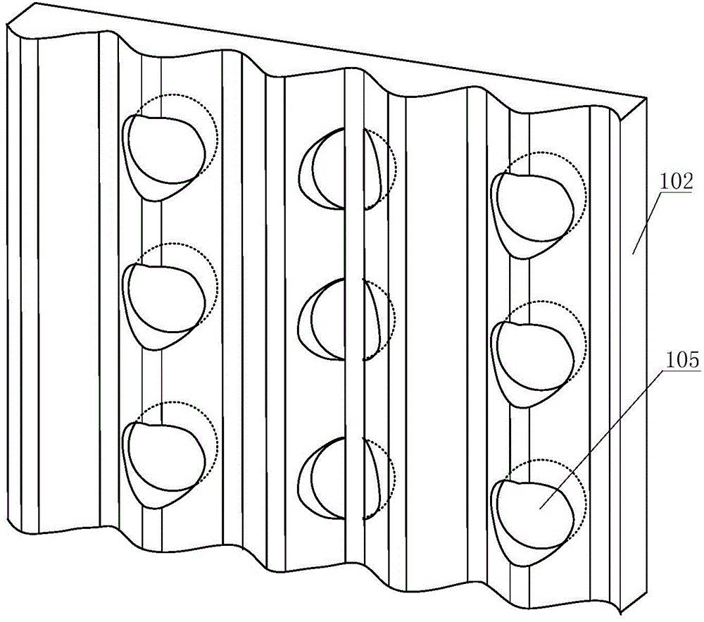
[0031] Embodiments of the present invention are described below in conjunction with the accompanying drawings. Such as figure 1 As shown, according to an embodiment of the present invention, the semiconductor power generation equipment using the waste heat of the flue gas at the tail of the boiler includes the flue at the tail of the boiler (101) and a thermoelectric power generation device (109). Among them, the thermoelectric power generation device (109) further includes a hot end surface (110), a cold end surface (102), a lead wire (103), a welding point (104), a flow deflector (106), a P-type semiconductor (107), an N-type The semiconductor (108) and the thermal insulation material (111) are provided with cooling holes (105) on the cold end surface (102).

[0032] The thermoelectric power generation device (109) is connected to the boiler tail flue (101) through a fixed layer of insulating material (111); The end surface (102) produces a temperature difference, so that ...


PUM


Abstract

The invention relates to a semiconductor power generation device using flue gas waste heat of a rear smoke channel of a boiler. The semiconductor power generation device comprises a boiler rear smoke channel (101) and a thermoelectric power generation device (109). The thermoelectric power generation device consists of a hot end surface (110), a cold end surface (102), a leading-out wire (103), welding points (104), guide plates (106), P type semiconductors (107), N type semiconductors (108), and a thermal insulation material layer (111). Cooling holes (105) are formed in the cold end surface. The thermoelectric power generation device is connected with the boiler rear smoke channel by the thermal insulation material layer. According to the thermoelectric power generation device, a temperature difference is generated between the hot end surface (110) formed by flue gas waste heat and the cold end surface (102) under an atmospheric temperature, so that the P type semiconductors and the N type semiconductors generate electromotive forces respectively. The P type semiconductors and the N type semiconductors are connected in series by the guide plates; and the generated electrical energy is outputted to the user based on the welding points and the leading-out wire. According to the invention, with the heat sensitivity of the semiconductors, the flue gas waste heat is utilized and the low-temperature waste heat is converted into the electric energy directly, so that no pollution is caused and installation is convenient; and the effect of energy conservation and emission reduction is realized well.

Description

technical field [0001] The invention relates to a device for recovering and utilizing waste heat of tail flue gas, in particular to a thermoelectric power generation device and semiconductor power generation equipment for recovering waste heat of tail flue gas and utilizing semiconductor thermal sensitivity to generate electricity. Background technique [0002] Under the premise that my country's energy is relatively scarce, it is necessary to increase energy conservation efforts. [0003] The exhaust gas temperature of the boiler is relatively high, generally between 150°C and 200°C, and it is a waste heat resource with great potential. [0004] The existing flue gas waste heat utilization device is mainly a low-pressure economizer, but because the temperature of the flue gas is too low and the heat transfer coefficient of the low-pressure economizer is small, a large heat transfer area is required, resulting in a bulky device and metal More consumables. [0005] The curr...

Claims


Application Information

Patent Timeline
Patent Type & Authority Applications(China)
IPC IPC(8): H02N11/00F27D17/00
CPCH02N11/002Y02P10/25
Inventor 王为术徐维晖朱晓静张鸣路统郭会军柳艺多
Owner NORTH CHINA UNIV OF WATER RESOURCES & ELECTRIC POWER
Why Eureka
Try Eureka