

Composition for forming solar cell electrode, and electrode produced from composition
A solar cell and composition technology, which is applied to conductive materials, circuits, electrical components and other directions dispersed in non-conductive inorganic materials, can solve problems such as difficulty in printing patterns, and achieve the effect of high aspect ratio
- Summary
- Abstract
- Description
- Claims
- Application Information
AI Technical Summary
Problems solved by technology
Method used
Image

Examples
specific Embodiment approach
[0055] In the following exemplary embodiments, each component of the present invention will be described in more detail. However, the exemplary embodiments are provided for understanding of the present invention and are not limited to the following embodiments. Other details not described in this application can be easily deduced by those skilled in the art, so they are omitted.
[0056] Composition for Solar Cell Electrodes
[0057] The solar cell electrode composition according to the present invention includes conductive powder (A), glass frit (B), organic vehicle (C) and thixotropic agent (D), and can be printed in a fine line width by screen printing Printed on the substrate, and has high conversion efficiency.
[0058] Now, each component of the solar cell electrode composition according to the present invention will be described in more detail.
[0059] (A) Conductive powder
[0060] As the conductive powder, any organic or inorganic powder having conductivity can b...
example 1
[0110] For the organic binder, 0.7wt% ethylcellulose (STD4, SDT200, Dow Chemical Company) was fully dissolved in 3.3wt% ester alcohol (Texanol) at 60°C to An organic vehicle was prepared, and the average particle diameter was 88wt% spherical silver powder (AG-4-8, Dowa Hightech Co.Ltd) of 2.0 μm, 2.7wt% low melting point crystallized glass powder ( Pb-Bi-Te-O) (average particle size 1.0 μm, and transition point 280° C.) and 0.6 wt % dispersant BYK145 (BYK-Chemie) and 0.4 wt % thixatrol ST (Eminence Co., Ltd.) was added to the organic vehicle, followed by mixing and kneading in a 3-roll kneader to prepare a solar cell electrode composition.
[0111] The composition is printed in a preset pattern on the front surface of the wafer by screen printing. The properties of the composition were measured by the following methods, and the results are shown in Table 2.
example 2 to example 5 and comparative example 1 to comparative example 3
[0113] A composition for a solar cell electrode was prepared in the same manner as in Example 1 except that the amounts of the components for the composition listed in Table 2 were used. Hereinafter, the compositions were printed by screen printing.
[0114] property measurement
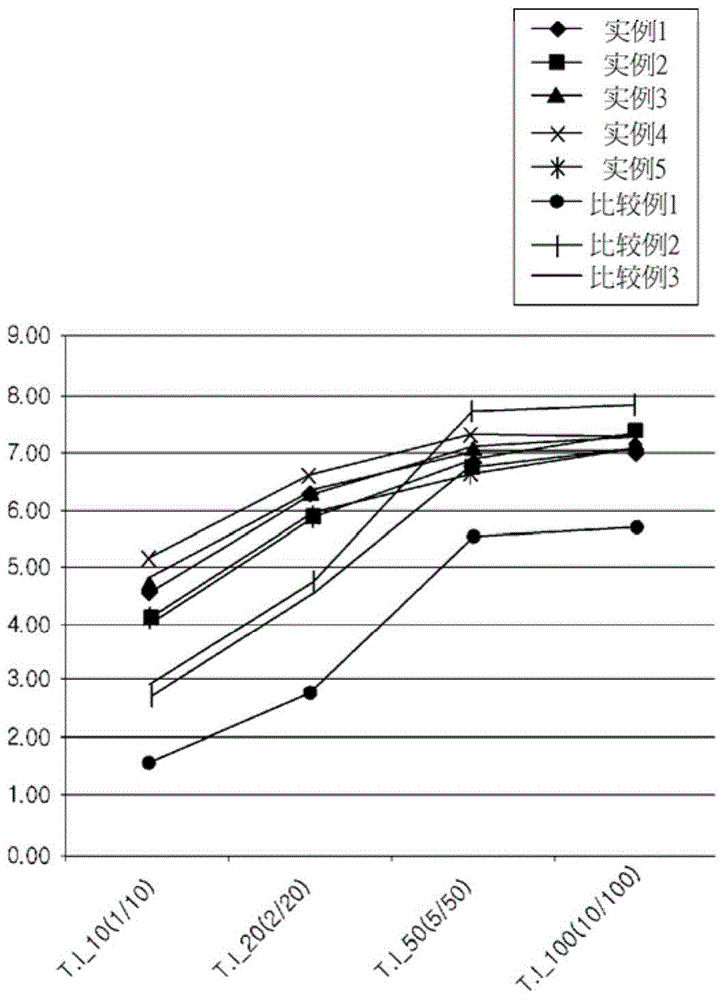
[0115] Measurement of Thixotropic Index (TI):
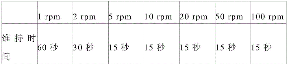
[0116] The thixotropic index was calculated using the ratio of the viscosity values measured at 23° C. using a No. 14 spindle by a rotational viscometer HBDV-II+Pro (Brookfield Co., Ltd.). For viscosity measurements, the sample cup is filled with sample and the mandrel is configured. After the temperature was stabilized for 5 minutes, the viscosity was measured at the following holding time.
[0117] Table 1
[0118]
[0119] The thixotropic index in Formula 1 to Formula 4 and the rate of change of the thixotropic index in Formula 5 to Formula 7 were calculated based on the measured viscosity values. The results are shown in Table 2 and figur...
PUM
| Property | Measurement | Unit |
|---|---|---|
| The average particle size | aaaaa | aaaaa |
| Line width | aaaaa | aaaaa |
| The average particle size | aaaaa | aaaaa |
Abstract
Description
Claims
Application Information