Supercharge Your Innovation With Domain-Expert AI Agents!

Spiral guide snow maker

A snow-making and spiral technology, which is applied in ice-making, lighting and heating equipment, recreational ice-making, etc., can solve the problems of high investment cost, high technical content, complex structure, etc., and achieve low investment cost, simple equipment structure and easy maintenance. The effect of low maintenance cost

Active Publication Date: 2015-09-16
湖州佳灏信息技术有限公司
View PDF5 Cites 0 Cited by
  • Summary
  • Abstract
  • Description
  • Claims
  • Application Information

AI Technical Summary

Problems solved by technology

[0003] With the improvement of people's living standards, people have more and more economic ability to travel and experience different sports at the same time. It is one of the sports that people like when skiing. Through skiing, people can experience the feeling of speed, exercise their bodies, and at the same time use People are happy. Ski resorts are mainly concentrated in northern China. In order to prolong their business hours, many ski resorts often use snowmaking machines to make snow when the temperature drops below zero to increase the shortage of natural snow. Traditional snowmaking The machine blows the water high into the air through a high-pressure fan. At high speed, the water becomes fine particles. Due to the low temperature, the water freezes quickly. This method requires a powerful fan, and at the same time, the snow generated during the The noise is very loud, and the equipment has high technical content, complex structure, and high investment cost. The market needs a small snowmaking equipment that can impact water into fine particles through the airflow. It is suitable for small ski resorts and can improve energy utilization. More energy saving and environmental protection, simple equipment structure, low investment cost, low maintenance cost, the diameter of the ice particles produced is small, making the snow softer

Method used


Image

  • Spiral guide snow maker
  • Spiral guide snow maker

Examples


Embodiment Construction

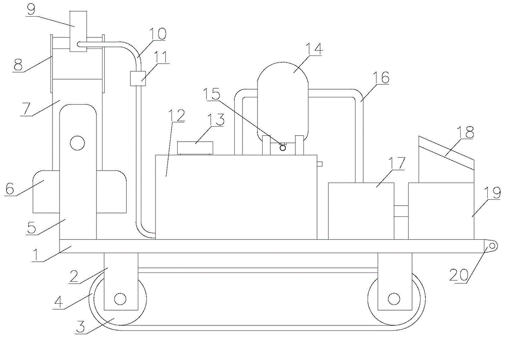
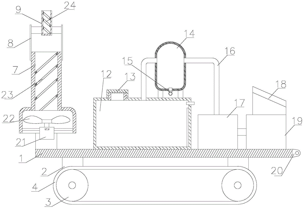
[0017] refer to figure 1 and figure 2 , a spiral-guided snowmaking machine of the present invention, comprising a seat plate 1, a wheel frame 2, a ground wheel 3, a snow belt 4, a snow spray device bracket 5, a fan housing 6, an air guiding tube 7, a water guiding tube bracket 8, Water guide cylinder 9, water pipe 10, solenoid valve 11, water tank 12, tank cover 13, gas storage bottle 14, drain valve 15, air guide pipe 16, air pump 17, electric control box 18, gasoline engine 19, traction ear 20, fan motor 21 , blade fan 22, air guide spiral plate 23 and water guide spiral plate 24, described seat plate 1 bottom is provided with wheel frame 2, and ground wheel 3 is installed on described wheel frame 2, and snow wheel 3 is installed on described ground wheel 3 Zone 4, the left side of the seat plate 1 is provided with a snow spraying device bracket 5, the snow spraying device bracket 5 is hingedly installed with an air guide tube 7, and the air guide tube 7 is provided with a...


PUM


Abstract

The invention discloses a spiral guide snow maker comprising an air guide barrel, a water guide barrel bracket, a water guide barrel, a water pipe, an electromagnetic valve, a water tank, a tank cover, an air storage bottle, a water escape valve, an air guide pipe, an air pump, an air guide spiral plate, and a water guide spiral plate. The lower portion of a base plate is provided with a wheel carrier. The wheel carrier is provided with a trailing wheel. The trailing wheel is provided with a snow crawler. The left side of the base plate is provided with a snow sprayer bracket. The lower portion of the air guide barrel is connected with a blower housing. A fan motor is arranged inside the blower housing. The air storage bottle is connected with the water tank through the air guide pipe. The right side of the water tank is provided with the air pump. The air pump is connected with the air storage bottle through the air guide pipe. A pressure sensor and a water level sensor are arranged inside the water tank. The spiral guide snow maker can impact the water into fine particles by the air flow; the spiral guide snow maker is suitable to be used in small-scale ski fields, and is able to increase the energy source utilization ratio; therefore, the spiral guide snow maker is more energy-saving and environment-friendly, with the maintenance cost being low and the produced ice particles being small in diameter; and accordingly the produced ice is softer.

Description

【Technical field】 [0001] The invention relates to the technical field of snowmaking equipment, in particular to the technical field of a spiral guide snowmaking machine. 【Background technique】 [0002] The traditional snowmaking machine is an electrical device that can quickly convert a large amount of liquid water into high-pressure atomized ice crystals. It is mainly used for artificial snowmaking, artificial skiing venues, and fire protection. Most are equipped with crawler wheels for easy movement, and are loaded with a thick and short snow spray barrel with a wide diameter. Most of them are equipped with crawler wheels for easy movement, and are equipped with a snow spray gun barrel with a wide diameter and a short diameter. [0003] With the improvement of people's living standards, people have more and more economic ability to travel and experience different sports at the same time. It is one of the sports that people like when skiing. Through skiing, people can expe...

Claims


Application Information

Patent Timeline
Patent Type & Authority Applications(China)
IPC IPC(8): F25C3/04
Inventor 石哲文
Owner 湖州佳灏信息技术有限公司
Features
  • R&D
  • Intellectual Property
  • Life Sciences
  • Materials
  • Tech Scout
  • Unparalleled Data Quality
  • Higher Quality Content
  • 60% Fewer Hallucinations
Learn More