D-shaped bolt U-shaped pipe high-pressure heat exchanger

A heat exchanger and bolt technology, applied in the field of U-shaped tube high pressure heat exchanger, can solve the problems of high manufacturing precision, corrosion failure, large cutting workload, etc., achieve rapid installation and disassembly, avoid thread seizure, reduce The effect of workload

Inactive Publication Date: 2015-09-16
BEIJING UNIV OF CHEM TECH
View PDF5 Cites 2 Cited by
  • Summary
  • Abstract
  • Description
  • Claims
  • Application Information

AI Technical Summary

Problems solved by technology

[0009] The technical problems to be solved by the present invention are: the bolted flange heat exchanger is not suitable for high temperature and high pressure occasions, and the assembly and disassembly process of the Ω seal ring heat exchanger requires a large amount of welding and cutting work, difficult disassembly and assembly, and is not corrosion-resistant. The heat exchange dead zone of the heat exchanger is large; the assembly and disassembly of the threaded locking ring heat exchanger requires special tools, and the machining volume of the main thread and other structures is large and the manufacturing precision is high. During the assembly and disassembly process, seizures are prone to occur, and assembly and disassembly are inconvenient , the tube box is bulky and the manufacturing cost is high; the welding part of the diaphragm seal plate of the diaphragm heat exchanger is easy to crack and corrode, and the main thread size is large under high pressure, which makes the tube box structure bulky and difficult to assemble and disassemble

Method used


Image

  • D-shaped bolt U-shaped pipe high-pressure heat exchanger
  • D-shaped bolt U-shaped pipe high-pressure heat exchanger
  • D-shaped bolt U-shaped pipe high-pressure heat exchanger

Examples


Embodiment Construction

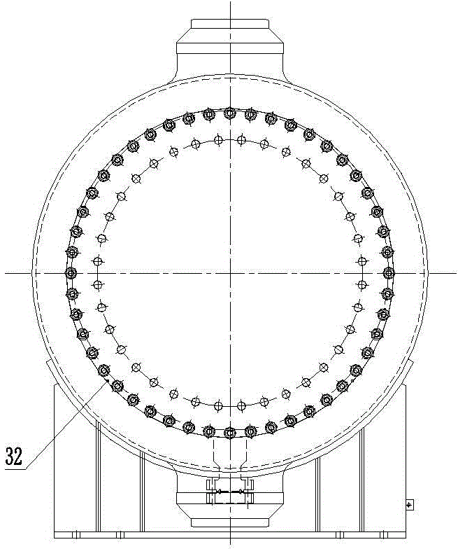
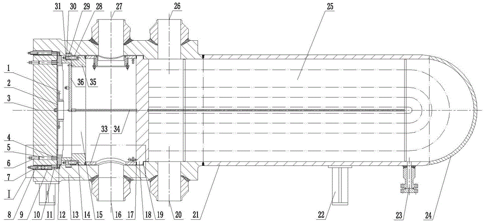
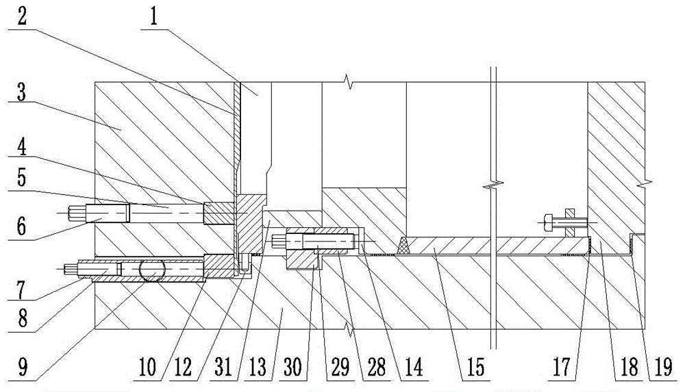
[0047] Such as Figure 1.1-1.2 As shown, the D-shaped bolt U-shaped tube high-pressure heat exchanger includes a shell-side cylinder 21 and a tube-box cylinder 13 , and a tube plate 18 is provided between the shell-side cylinder 21 and the tube-box cylinder 13 . The shell side cylinder 21 is provided with a support 22, a drain hole 23, a shell side inlet 26 and a shell side outlet 20, and a tube bundle 25 is arranged between the shell side inlet 26 and the shell side outlet 20; Tube-side inlet 16 , tube-side outlet 27 and support 11 . An inner sealing gasket 19 is provided between the tube sheet 18 and the tube box body 13 , and a gasket 17 is provided between the tube sheet 18 and the split box 15 .

[0048] A range box 15 is arranged inside the pipe box cylinder body 13 , and the range box 15 includes a range box cover plate 36 (a semicircle in cross section) and a range partition 34 . The half circumference of the split-range box cover plate 36 is connected with the suppo...


PUM


Abstract

The invention discloses a D-shaped bolt U-shaped pipe high-pressure heat exchanger. The D-shaped bolt U-shaped pipe high-pressure heat exchanger is mainly used for solving the problem existing in an existing bolt flange type heat exchanger, an existing omega sealing ring heat exchanger, an existing screw locking ring heat exchanger and an existing diaphragm seal heat exchanger. A flat deck roof (3) is arranged at the end portion of a pipe chamber cylinder (13), and the pipe chamber cylinder (13) is connected with the flat deck roof (3) through a round of eccentrically and uniformly distributed D-shaped bolts (7) to bear axial force. The D-shaped bolts (7) can be fixed into about 3/4 threaded holes of the flat deck roof or the end portion of the pipe chamber cylinder, and an outer sealing gasket (12) can select a winding gasket or a wave tooth composite gasket or a stainless steel C-shaped sealing ring. Inner ring compression bolts (6) and outer ring compression bolts (8) are arranged on the flat deck roof, internal bolts (29) are arranged in grooves of the pipe chamber cylinder, both the inner ring compression bolts and the internal bolts can provide sealing force for an inner sealing gasket (19), and the outer ring compression bolts provide sealing force for the outer sealing gasket. The D-shaped bolt U-shaped pipe high-pressure heat exchanger is mainly used for the heat exchange process of petroleum refining hydro-treatment technology.

Description

technical field [0001] The invention relates to a U-shaped tube high-pressure heat exchanger used in the petroleum processing industry. Background technique [0002] At present, with the increasingly poor quality of crude oil, the rapid development of the national economy and the continuous improvement of environmental protection requirements, the demand for the development of low-sulfur clean fuels is becoming increasingly urgent. Hydrotreating processes such as hydrofining, hydrocracking, and hydrodesulfurization are important means to change the properties of oil products, and the hydrogenation heat exchanger is an indispensable equipment in the hydrogenation process, and is also an important energy-saving and consumption-reducing equipment . [0003] The medium in the hydrogenation unit is flammable and explosive, and the working environment of the equipment is harsh: high temperature, high pressure, and the medium contains hydrogen and hydrogen sulfide, requiring the e...

Claims


Application Information

Patent Timeline
Patent Type & Authority Applications(China)
IPC IPC(8): F28D7/06F28F11/02F28F9/26
Inventor 陈平罗聪徐雪倩周淑敏
Owner BEIJING UNIV OF CHEM TECH
Why Eureka
Try Eureka