An isolated high frequency pulse generator

A high-frequency pulse generator technology, applied in the field of isolated high-frequency pulse generators, can solve problems such as noise disturbance, low frequency matching, lack of isolation protection for pulse generators, etc., and achieve the effect of improving versatility

Active Publication Date: 2018-03-06
SICHUAN HONGFAN SPECIAL EQUIP ENG CO LTD
View PDF4 Cites 0 Cited by
  • Summary
  • Abstract
  • Description
  • Claims
  • Application Information

AI Technical Summary

Problems solved by technology

[0003] In view of the above-mentioned prior art, the purpose of the present invention is to provide an isolated high-frequency pulse generator, which aims to solve the lack of isolation protection of the existing pulse generator, the existence of noise disturbance, poor anti-interference ability, low frequency matching and no universal sex and other technical issues

Method used


Image

  • An isolated high frequency pulse generator
  • An isolated high frequency pulse generator
  • An isolated high frequency pulse generator

Examples


Embodiment 1

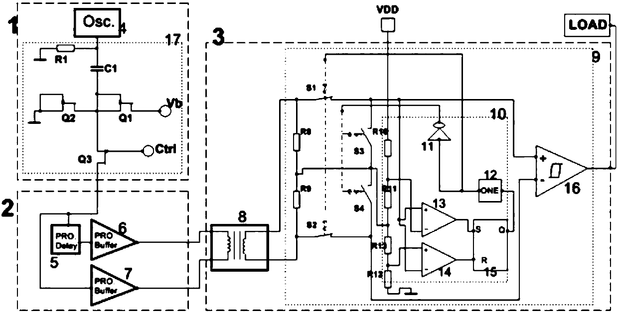
[0022] According to the operating frequency of the external load, a programmable delayer 5, a first programmable buffer 6 and a second programmable buffer 7 are set to complete frequency matching.

[0023] The digital isolation unit 3 includes a coil device 8 whose primary winding is connected to the output port of the frequency matching unit 2 , and a noise reduction unit 9 whose input port is connected to the secondary winding of the coil device 8 . The noise reduction unit 9 includes a first switch S1 connected in series with the secondary winding of the coil device 8, a second switch S2 and a Schmitt trigger 16, forming an effective output loop; including a parallel connection with the secondary winding of the coil device 8 The third switch S3 and the fourth switch S4 connected in series with the third switch S3 constitute a circuit for cutting off the noise of the secondary winding of the short-circuited coil device 8; it also includes an input feedback timing unit 10 for ...

Embodiment 2

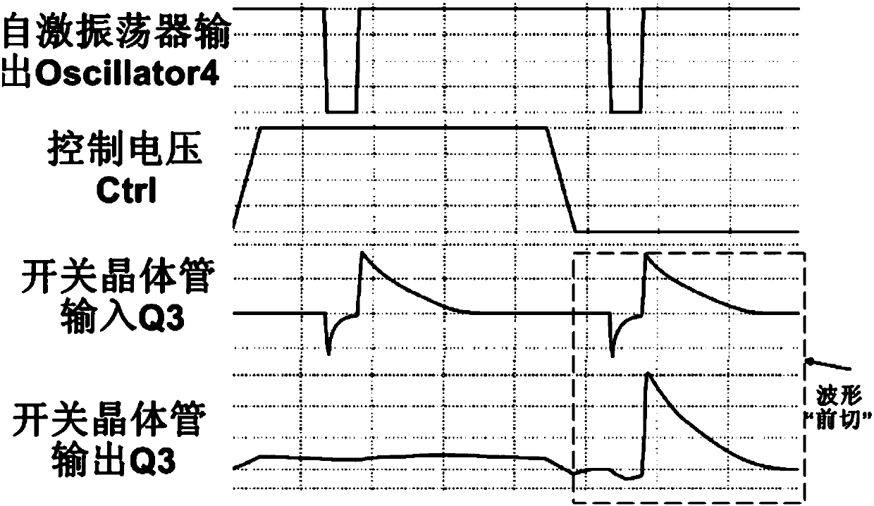
[0025] image 3 For the pulse generation waveform change diagram of the present invention, the self-excited oscillator 4 sends an oscillating square wave pulse, the control voltage Ctrl applies a high level, and the switching transistor Q3 has no output wave; the control voltage Ctrl cancels the high level, and the switching transistor Q3 "cuts forward" After the waveform is obtained an oscillating output.

Embodiment 3

[0027] Figure 4 It is a schematic diagram of the implementation of the transmission pulse of the present invention. After the pulse wave is output from the secondary winding of the coil device 8, the electromagnetic interference of the coil causes the noise oscillation opposite to the pulse wave electric parameter to occur at the end of the pulse waveform. At this time, the input feedback timing unit 10 is based on the high level of the pulse wave The pulse width obtains the input timing, which is fed back to the first switch S1 and the second switch S2, while the third switch S3 and the fourth switch S4 are turned off, so that the pulse wave is output. When the timing ends, the third switch S3 and the fourth switch S4 When it is turned on, the coil device 8 is short-circuited, so that the noise oscillation at the tail of the pulse waveform is cut off, and the "back-cut" of the pulse waveform is realized.

[0028] The invention has beneficial effects such as isolation protect...


PUM


Abstract

An isolated high-frequency pulse generator, the invention relates to the field of integrated circuits, which aims to solve the existing pulse generator lack of isolation protection, noise disturbance, poor anti-interference ability, low frequency matching and lack of versatility and other technologies question. The circuit structure features of the invention include a pulse generating unit: generating a monostable high-frequency modulation pulse; a frequency matching unit: having the function of matching a high-frequency pulse to a low-frequency load; a digital isolation unit: having the functions of isolation protection and noise reduction; pulse generation The output end of the unit is connected to the input end of the frequency matching unit, and the output port of the frequency matching unit is connected to the input port of the digital isolation unit. The invention is used to generate pulses.

Description

technical field [0001] The invention relates to the field of integrated circuits, in particular to an isolated high-frequency pulse generator. Background technique [0002] Pulse generators are often used in electronic systems such as detection and communication. Most of the existing pulse generators are non-isolated and directly connected to the load circuit; in testing applications, the electronic device under test may have various circuit problems. When the load is short-circuited, the strong current may damage the pulse generator, or even Burn out the pulse generator. For pulse generators that use isolation, they are divided into optocoupler and coil coupling; optocoupler, there are problems such as light-emitting diodes are easy to age, and the operating frequency is low; the existing coil-coupled pulse generator lacks excellent rectifying circuits and frequencies Matching circuit; the rectifying circuit itself has electromagnetic interference, cannot complete the wav...

Claims


Application Information

Patent Timeline
Patent Type & Authority Patents(China)
IPC IPC(8): H03K3/02
Inventor 王雨涵李国
Owner SICHUAN HONGFAN SPECIAL EQUIP ENG CO LTD
Why Eureka
Try Eureka