Nutrition pot continuous manufacturing machine

A nutrition bowl and making machine technology, applied in application, cultivation, agriculture, etc., can solve the problems of separation, complicated operation procedures, need to stack and other problems, and achieve the effect of no exhaust gas emission and small volume

Active Publication Date: 2015-09-23
武汉长江控制设备研究所有限公司
View PDF9 Cites 10 Cited by
  • Summary
  • Abstract
  • Description
  • Claims
  • Application Information

AI Technical Summary

Problems solved by technology

[0005] Semi-automatic nutrition bowl making machine: This method is improved in manual production, changing from one model to a group of models, increasing the number of nutrition bowls made at a time, but the operation procedure is complicated, and the model is too heavy, which is not easy to operate, and It needs to be stacked, and the efficiency is not high
[0006] Mechanical nutrition bowl making machine: This machine refers to the production process of honeycomb coal making machine, which is much more efficient than the above two methods, and can reach 20,000 pieces / hour / set. The best results can only be achieved with the full cooperation of 4 people
[0007] Industrial nutrition bowl making machine: This model has the advantages of automatic lumping, multi-seed on-demand, and tray shipment, and high efficiency. However, this model is too large and cannot be moved. It can only be operated in the factory, which is inconvenient. It is used in rural areas, which is out of the actual situation in rural areas, and it is not easy to promote in rural areas.
Moreover, the nutrient soil and the shaped nutrient bowl need to be transported, which increases the production cost of the nutrient bowl

Method used


Image

  • Nutrition pot continuous manufacturing machine
  • Nutrition pot continuous manufacturing machine
  • Nutrition pot continuous manufacturing machine

Examples


Embodiment Construction

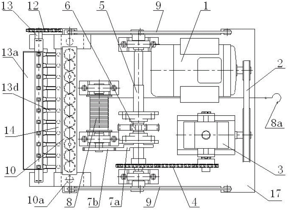
[0025] The nutritional bowl continuous making machine of the present invention mainly has two action processes: the first action process is intermittent walking of the nutritional bowl making machine; the second action process is bowl making and seed distribution. Two action processes circulate repeatedly, constitute the whole action process of the present invention.

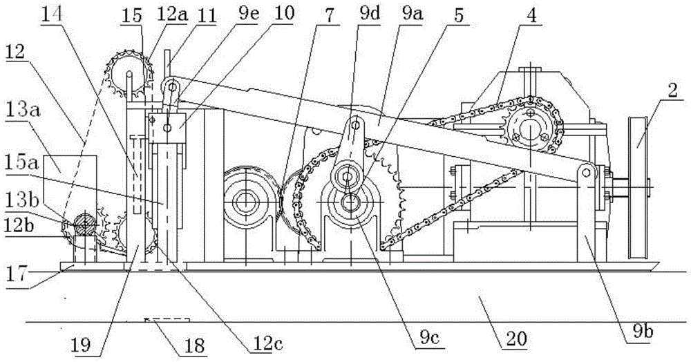
[0026] Drive part: The direct drive part of the two action processes is the main drive shaft 5, such as figure 1 As shown, it is driven by the motor 1, the belt transmission mechanism 2, the reducer 3 and the chain transmission mechanism 4. The whole set of design above is mainly to reduce the speed of the motor 1 to the main drive shaft 5 and increase the torque to The design requirements of the nutritional bowl making machine are met.

[0027] Intermittent walking part: this part is powered by the main transmission shaft 5, further decelerates through the gear transmission mechanism 6, and then realizes the i...


PUM


Abstract

The invention discloses a nutrition pot continuous manufacturing machine comprising a belt transmission mechanism, chain transmission mechanisms, a gear transmission mechanism, a ratchet transmission mechanism, a connection rod transmission mechanism, and the like. A power part adopts an AC motor 1. The AC motor 1 is connected with the belt transmission mechanism 2. Through speed reducing of a reducer 3, a first chain transmission mechanism 4 drives a main transmission shaft 5. The main transmission shaft 5 drives a reel 8 through the gear transmission mechanism 6 and the ratchet transmission mechanism 7. The reel rolls up a steel wire rope hanged by a hook. An entire nutrition pot manufacturing machine travels forward along the direction of the steel wire rope. The main transmission shaft 5 drives the connection rod transmission mechanism 9 to move downwards. A nutrition pot manufacturing mechanism 10 presses to form nutrition soil. The main transmission shaft 5 drives the connection rod transmission mechanism 9 to move upwards. A push plate mechanism 11 pushes out formed nutrition soil. A second chain transmission mechanism 12 acts synchronously with the nutrition pot manufacturing mechanism 10, such that a seed distribution shaft 13b is driven and performs seed distribution when the nutrition pot manufacturing mechanism 10 moves downwards.

Description

technical field [0001] The invention relates to a nutrient pot continuous production machine. The nutrient pot is used as the base soil for cultivating seedlings, which is suitable for various crops (cotton, watermelon, flowers, fruit trees, etc.), not only for experimental seedling cultivation, but also for For the cultivation of seedlings in large-scale agricultural production, the function of the nutrient bowl making machine is to plant seeds and make nutrient bowls. Background technique [0002] Cotton seedling transplanting is an important technical link to achieve high-yield and high-efficiency cotton. It has been widely used in cotton areas in the Yellow River Basin and the middle and lower reaches of the Yangtze River, and has achieved good yield-increasing effects. The basic methods of cotton seedlings include early sowing seedlings, soilless seedlings, plug seedlings and nutrient pot seedlings. Among them, nutrient pot seedling cultivation is a method with the wid...

Claims


Application Information

Patent Timeline
Patent Type & Authority Applications(China)
IPC IPC(8): A01G9/10
Inventor 潘熙和丁克起王爱生方斌臣黄业华刘立祥程玉婷郑兴华于秋菊叶炜聂伟
Owner 武汉长江控制设备研究所有限公司
Why Eureka
Try Eureka