Automatic soldering tin machine for terminal pin of transformer

A technology of lead pins and transformers, applied in welding equipment, auxiliary devices, printed circuits, etc., can solve the problems of accumulating impurities, affecting normal operations, and high labor costs, and achieves the advantages of convenient cleaning or replacement, improved work efficiency, and quality assurance Effect

Inactive Publication Date: 2015-09-23
江西耀润磁电科技有限公司
View PDF5 Cites 43 Cited by
  • Summary
  • Abstract
  • Description
  • Claims
  • Application Information

AI Technical Summary

Problems solved by technology

The existing technology is to manually solder the lead pins. This soldering method has the following disadvantages: 1. The stability of manual soldering is poor, and the soldering depth of the lead pins is not easy to control, resulting in differences in the performance of the same batch of transformers; 2. Manual soldering The work efficiency of soldering is low, and the labor cost is high
The existing automatic soldering machine has the following disadvantages: 1. After repeated use, the tin liquid in the tin bath is easy to accumulate impurities and affect the normal operation. In addition, it is necessary to frequently remove excess oxides on the surface of the tin liquid to ensure the quality of the solder
The fully automatic soldering machine can not be used for transformers, so the lead pins of transformers can be welded side by side, so there are limitations and the scope of application is small

Method used


Image

  • Automatic soldering tin machine for terminal pin of transformer
  • Automatic soldering tin machine for terminal pin of transformer
  • Automatic soldering tin machine for terminal pin of transformer

Examples


Embodiment

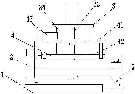
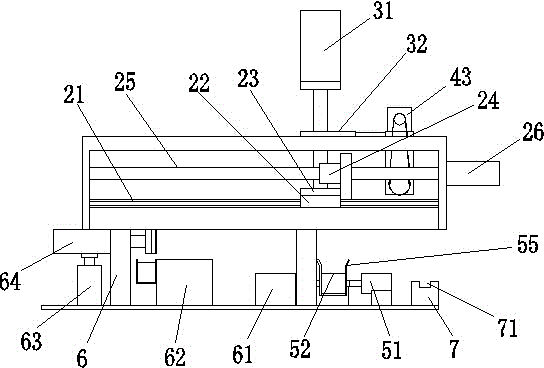
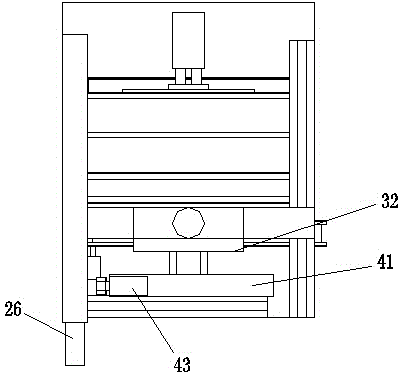
[0038]It includes a frame, a traverse device, a lifting device, a clamping device, a soldering device and a conveying device. The traverse device includes a guide rail, a slider, a traverse plate, a sliding sleeve, a traverse screw and a traverse motor. The guide rail is fixed on the frame, the slider fits on the guide rail and can move linearly along the guide rail, the traversing plate is fixed on the slider, and the sliding sleeve is sleeved on the traversing screw rod and fixed with the traversing plate , the traversing motor is connected with the traversing screw; the lifting device includes a lifting motor, a lifting plate, a lifting screw and a lifting frame with a guide rod, and the lifting frame is fixed on the traversing plate and is controlled by the traversing plate Drive the lifting device to move horizontally as a whole, the lifting motor is fixed on the lifting frame and connected with the lifting screw, the lifting plate passes through the guide rod and cooperat...


PUM


Abstract

The invention discloses an automatic soldering tin machine for a terminal pin of a transformer. The automatic soldering tin machine for the terminal pin of the transformer comprises a machine frame, a transverse movement device, a lifting device, a clamping device, a soldering tin device and a feeding device. The transverse movement device comprises guide rails, a sliding block is arranged on the guide rails, the sliding block is connected with a transverse movement plate, the transverse movement plate is connected with a sliding sleeve, the sliding sleeve is connected with a transverse movement screw, and one end of the transverse movement screw is connected with a transverse movement motor. The lifting device comprises a lifting motor, the lifting motor is installed on a lifting frame, and the lifting frame is connected with the transverse movement plate through a guide rod; the output end of the lifting motor is connected with a lifting lead screw, and a lifting plate is arranged on the lifting lead screw. The clamping device comprises a support connected with the lifting plate, a transmission motor is arranged on the support, the output end of the transmission motor is in transmission connection with a clamping part through a belt, and the clamping part is hinged to the lower portion of the support. The soldering tin device comprises a scaling powder groove and a molten tin bath. The automatic soldering tin machine for the terminal pin of the transformer has the advantages of being simple in structure, reasonable in design, high in automation degree and stable in operation; in addition, the working efficiency is high, discharging is order, and the terminal pin of the transformer can be welded edge by edge.

Description

Technical field [0001] The invention involves an automatic welding machine with a transformer leading foot, especially an automatic solder machine for transformer leading to a mobile phone charger. Background technique [0002] The transformer used for the mobile phone charger includes a magnetic core, and a leading pin is set on the magnetic core.Welds are needed during production.The existing technology is to carry out welds through artificially to the lead. This welding method has the following shortcomings: 1. Poor stability of artificial welds, and the depth of the welding of the leading feet is not easy to control, resulting in the difference in performance of the same batch of transformers;Welds have low work efficiency and high labor costs. [0003] There are also automatic welds for automatic welds to solve the above problems.The existing automatic welding machine has the following shortcomings: 1. After repeated use of tin grooves, it is easy to accumulate impurities an...

Claims


Application Information

Patent Timeline
Patent Type & Authority Applications(China)
IPC IPC(8): B23K3/00B23K3/08B23K101/42
CPCB23K3/00B23K3/08B23K3/082B23K3/087B23K2101/42
Inventor 茅柳强
Owner 江西耀润磁电科技有限公司
Why Eureka
Try Eureka