Internal and external circular air assisted electrospinning nozzle unit

A technology of spinning nozzle and air flow, which is applied in the field of electrostatic spinning nozzle devices assisted by inner and outer double-circle airflow, which can solve the problems of easy blockage of capillary tubes, achieve high spinning efficiency, strong controllability, and reduce the critical voltage value

Active Publication Date: 2015-09-23
烟台森森环保科技有限公司 +1
View PDF8 Cites 6 Cited by
  • Summary
  • Abstract
  • Description
  • Claims
  • Application Information

AI Technical Summary

Problems solved by technology

[0005] The purpose of the present invention is to propose a kind of inner and outer double ring air flow assisted electrospinning nozzle device, through the drafting effect assisted by the inner and outer double ring air flow, the feed liquid at the middle ring feed liquid outlet is spun into nanofibers in a high-voltage electrostatic field, which is relatively Compared with the single-needle spinning method, it not only solves the problem of easy blockage of the capillary, but also greatly improves the fiber diameter and fiber yield

Method used


Image

  • Internal and external circular air assisted electrospinning nozzle unit
  • Internal and external circular air assisted electrospinning nozzle unit
  • Internal and external circular air assisted electrospinning nozzle unit

Examples


Embodiment 1

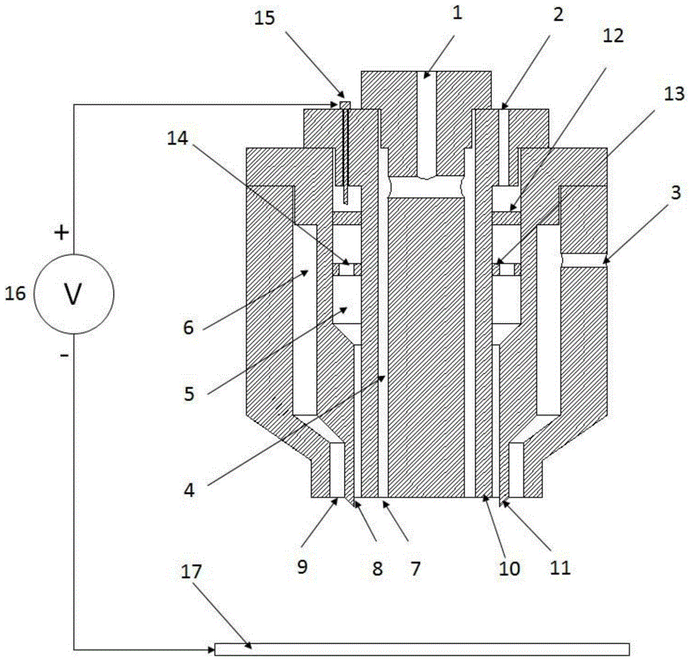
[0033] The schematic diagram of embodiment 1 is as figure 1 Shown, at first, by adding the powder of PVDF in the mixed solvent of acetone and DMF, the PVDF spinning stock solution that concentration is 13%w / v is prepared, and the molecular weight of PVdF is 500,000, and the viscosity range of spinning stock solution is 1200± 50cP.

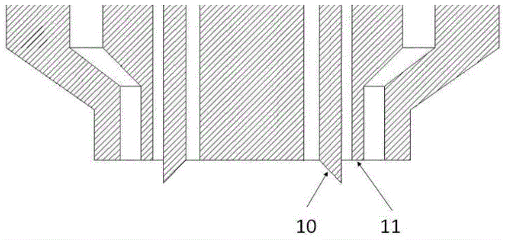
[0034] In this embodiment, the lower end of the third component 103 is longer than the lower end of the second component 102, and has a tapered end structure, that is, the outer wall 11 of the material liquid outlet of the spinning nozzle device is 1.5 mm longer than the inner wall 10 of the material liquid outlet, and For the end cone structure, such as figure 2 As shown, a discharge tip is formed; the receiving electrode 17 is a stainless steel plate, and the surface of the stainless steel plate is wrapped with aluminum foil to facilitate sample collection. First, the positive pole of the high-voltage power supply V is connected to the positive...

Embodiment 2

[0040] The schematic diagram of this embodiment is as figure 1 Shown, at first, by adding the powder of PVDF in the mixed solvent of acetone and DMF, the PVDF spinning stock solution that concentration is 13%w / v is prepared, and the molecular weight of PVdF is 500,000, and the viscosity range of spinning stock solution is 1200± 50cP.

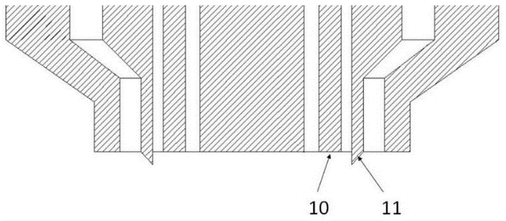
[0041] In this example, if image 3 As shown, the lower end of the second assembly 102 is longer than the lower end of the third assembly 103, and is a tapered end structure, that is, in the case of the spinning nozzle device, the inner wall 10 of the material liquid outlet is 2 mm longer than the outer wall 11 of the material liquid outlet, and the material liquid outlet is 2 mm longer than the outer wall 11 of the material liquid outlet. The inner wall of the liquid outlet is 2mm thick and has a tapered end structure, forming a discharge tip. The receiving electrode 17 is a stainless steel plate, and the surface of the stainless steel plate ...


PUM


Abstract

The invention belongs to the field of electrospinning and relates to an internal and external circular air assisted electrospinning nozzle unit, comprising a nozzle body and a positive electrode. The nozzle body is composed of a first component, a second component, a third component and a fourth component nested to one another and detachably arranged from inside to outside. The four components of the nozzle body form an internal circular air passage, an external circular air passage, a middle circular liquid passage and an internal circular air inlet; an external circular air outlet and an external circular liquid outlet are concentrically circular; a guide plate is disposed within the middle circular liquid passage. The positive electrode extends into the middle circular liquid passage and contacts liquid. The nozzle unit is assisted by both internal and external air flows, is simple in structure, high in controllability and good in airtightness, helps avoid volatilizing of solvents in the liquid during spinning, has the yield up to ten times as high as the needle type, roller type or spiral type electrospinning unit, and is suitable for continuous industrial production of nanofibers.

Description

technical field [0001] The invention belongs to an electrostatic spinning nozzle device in the field of electrostatic spinning, in particular to an electrostatic spinning nozzle device assisted by inner and outer double-circle airflow. Background technique [0002] Electrospinning technology was first proposed in the US patent US1975504 in 1930. It is a spinning technology that uses electrostatic field force to prepare nanofibers. It was officially defined as electrospinning technology in 1993; its working principle is: polymer The solution or melt is extruded through a needle or nozzle and placed in a high-voltage electrostatic field. Under the stretching action of the electric field force, a Taylor cone is formed to generate a jet. The thin stream is highly stretched before reaching the receiving device. The solvent in the solution Evaporate or melt solidify, and finally form microfibers on the receiving device. Since the electrospinning method has many unique advantages ...

Claims


Application Information

Patent Timeline
Patent Type & Authority Applications(China)
IPC IPC(8): D01D5/00
Inventor 刘千祥邱凯丽
Owner 烟台森森环保科技有限公司
Why Eureka
Try Eureka