Automatic speed changer

A technology of automatic transmission and transmission, which is applied in the direction of vehicle gearboxes, gearboxes, transmissions, etc., and can solve the problems of reduced system reliability, increased system cost and volume, etc.

Active Publication Date: 2015-09-23
JING JIN ELECTRIC TECH CO LTD +1
View PDF7 Cites 33 Cited by
  • Summary
  • Abstract
  • Description
  • Claims
  • Application Information

AI Technical Summary

Problems solved by technology

At present, the shift actuator of the second-speed transmission adopts electric, pneumatic or hydraulic forms, which increases the cost and volume of the system, and reduces the reliability of the system

Method used


Image

  • Automatic speed changer
  • Automatic speed changer
  • Automatic speed changer

Examples


Embodiment 1

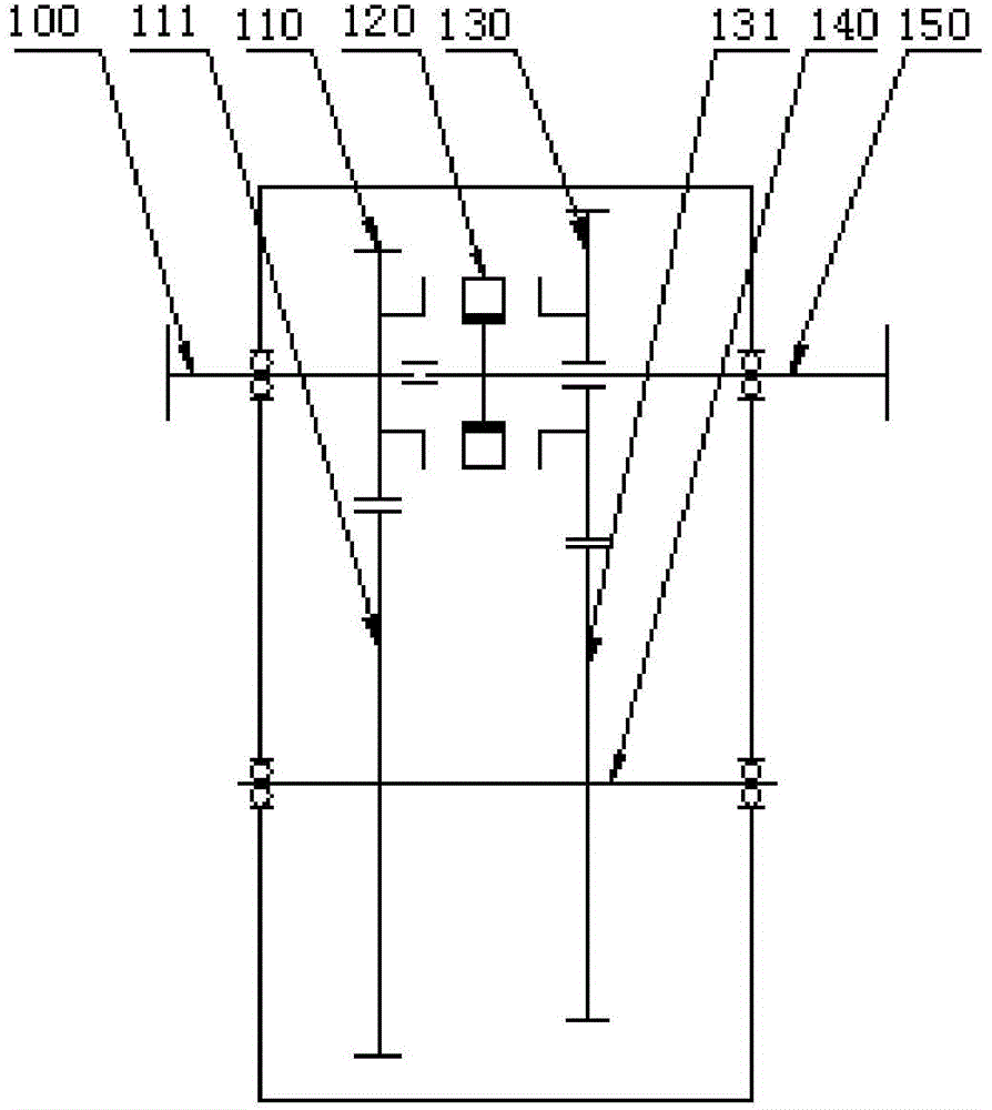
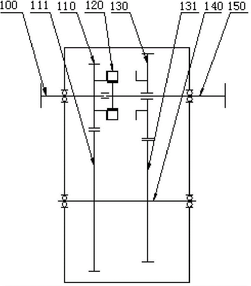
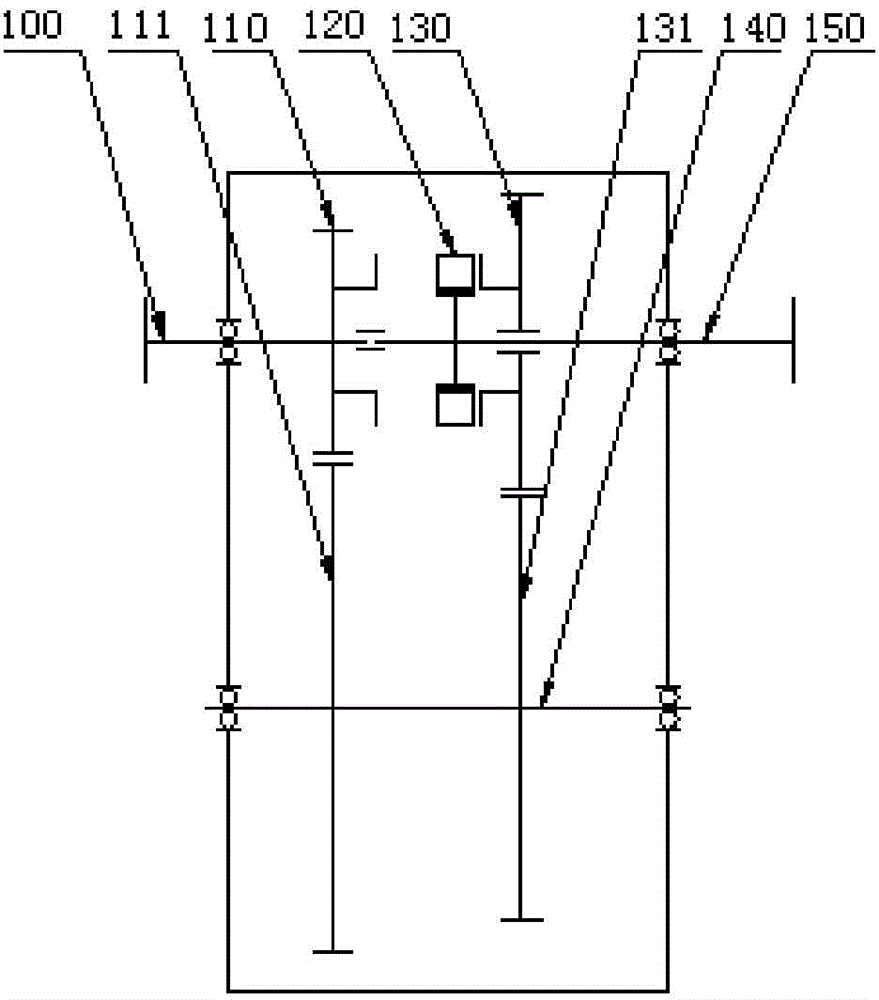
[0083] figure 1 It is a schematic structural diagram of the two-speed automatic transmission in Embodiment 1 of the present invention. figure 2 It is a transmission diagram of the second gear of the two-speed automatic transmission in Embodiment 1 of the present invention; image 3 It is a transmission diagram of the first gear of the two-speed automatic transmission in Embodiment 1 of the present invention.

[0084] see figure 1 , The automatic transmission in Embodiment 1 includes: a first double-face tooth combined chainring 120 and a fixed-axis gear train with two-stage reduction. The two-stage deceleration fixed-axis gear train includes: a transmission input shaft 100, a transmission intermediate shaft 140, a transmission output shaft 150, a combination tooth 110 on the right end face of the first external gear, a combination tooth 130 on the left end face of the first external gear, a first gear 111 and a second gear 131 .

[0085] Among them, the transmission input...

Embodiment 2

[0094] The specific structure of the double-face tooth combined toothed plate of the present invention can be easily extended to third gear, fourth gear, fifth gear, sixth gear and so on. In the second embodiment, the structure extended from the second-speed automatic transmission to the third-speed automatic transmission is given.

[0095] Figure 4 It is a schematic structural diagram of the three-speed automatic transmission in Embodiment 2 of the present invention. Such as Figure 4 As shown, the realization of the three-speed automatic transmission is based on the two-speed automatic transmission in the first embodiment above, adding a one-stage deceleration fixed-axis gear train and a combined tooth plate 250 with end teeth. That is to say, the three-speed automatic transmission in the second embodiment includes a transmission input shaft 100, a transmission intermediate shaft 140, a transmission output shaft 150, a combination tooth 110 for the right end face of the f...

Embodiment 3

[0109] The specific structure of the double-face tooth combination chainring of the present invention can be easily extended to third gear, fourth gear, fifth gear, sixth gear and so on. This embodiment describes in detail how to extend from a two-speed automatic transmission to a four-speed automatic transmission.

[0110] Figure 5 It is a schematic structural diagram of the four-speed automatic transmission in Embodiment 3 of the present invention. Such as Figure 5 As shown, the four-speed automatic transmission is realized on the basis of the two-speed automatic transmission in the first embodiment above by adding another two-stage reduction and a second double-end face tooth combined chainring 350 .

[0111] Such as Figure 5 As shown, the four-speed automatic transmission in the third embodiment includes a transmission input shaft 100, a transmission intermediate shaft 140, a transmission output shaft 150, a combination tooth 110 on the right end face of the first ex...


PUM


Abstract

The invention discloses an automatic speed changer. The automatic speed changer comprises a double-end-face tooth combined fluted disc and a two-level speed reduction fixed shaft wheel train. A gear shifting mechanism of the speed changer is the double-end-face tooth combined fluted disc and is provided with double-end-face teeth including the left end face teeth and the right end face teeth. The double-end-face tooth combined fluted disc axially moves on an output shaft of the speed changer, the left end face teeth and the right end face teeth of the double-end-face tooth combined fluted disc are engaged with end face teeth of a one-level speed reduction gear and a two-level speed reduction gear respectively, the two-gear position and the one-gear position are achieved, and when the left end face teeth and the right end face teeth of the double-end-face tooth combined fluted disc are not combined with the end face teeth of the one-level speed reduction gear and the two-level speed reduction gear, the speed changer is at a neutral position. According to the technical scheme, compared with a traditional AMT, a synchronizer is removed, the structure is simple, reliability is high, the gear shifting time is short, the gear shifting impact is small, the production cost is low, and industrialization is easy to achieve. The gear arrangement mode of the speed changer is simple, the axial size is short, the occupied space is small, the weight is low, and the automatic speed changer conforms to the development trend of light weight and energy saving.

Description

technical field [0001] The invention relates to the field of new energy vehicles, in particular to an automatic transmission. Background technique [0002] With the rapid development of new energy vehicles, the performance requirements of the whole vehicle are constantly increasing, such as power, ride comfort and driving range. In order to meet this requirement, the new energy power transmission system needs to be equipped with an automatic transmission. [0003] At present, the automatic transmission of new energy vehicles mostly adopts the technical route improved on the basis of the traditional automatic transmission of internal combustion engine vehicles. Automatic transmissions in the four traditional fields, including hydraulic automatic transmission (AT), continuously variable transmission (CVT), electromechanical automatic transmission (AMT), and dual clutch automatic transmission (DCT), are all used in the field of new energy vehicles. [0004] However, these tra...

Claims


Application Information

Patent Timeline
Patent Type & Authority Applications(China)
IPC IPC(8): F16H3/32F16H57/02F16H57/023F16H61/28
CPCF16H3/32F16H57/02F16H57/023F16H61/28F16H2061/2853F16H3/0915F16H2003/0811F16H2200/0021F16H2200/0034F16H2200/0039F16H2200/0043F16H3/12F16H63/32
Inventor 余平王婷
Owner JING JIN ELECTRIC TECH CO LTD
Why Eureka
Try Eureka