
Single particle effect detection method and system

A single-event effect and detection method technology, applied in the field of electronics, can solve the problem of inability to accurately measure the correlation between single-event effects and peripheral circuits, etc.

Active Publication Date: 2015-09-23
FIFTH ELECTRONICS RES INST OF MINIST OF IND & INFORMATION TECH
View PDF5 Cites 19 Cited by
  • Summary
  • Abstract
  • Description
  • Claims
  • Application Information

AI Technical Summary

Problems solved by technology

[0007] Based on this, it is necessary to provide a single event effect detection method and system for the problem that the above test method cannot accurately measure the relationship between the single event effect and the peripheral circuit.

Method used


Image

  • Single particle effect detection method and system
  • Single particle effect detection method and system
  • Single particle effect detection method and system

Examples


Embodiment Construction

[0021] Although the steps in the present invention are arranged with labels, they are not used to limit the order of the steps. Unless the order of the steps is clearly stated or the execution of a certain step requires other steps as a basis, the relative order of the steps can be adjusted.

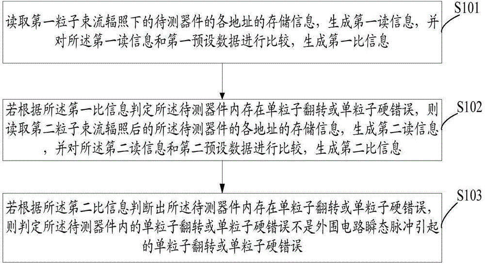
[0022] see figure 1 , figure 1 It is a schematic flow chart of the first embodiment of the single event effect detection method of the present invention.

[0023] The single event effect detection method described in this embodiment may include the following steps:

[0024] Step S101, read the storage information of each address of the device under test irradiated by the first particle beam, generate the first read information, and compare the first read information with the first preset data to generate the first than information, the device under test has been powered on and written with the first preset data.

[0025] Step S102, if it is determined according to the first ratio info...


PUM


Abstract

The present invention relates to a single particle effect detection method and system. The method comprises: reading storage information of addresses of components to be detected under irradiation of a first particle beam, generating first read information, comparing the first read information with first preset data, and generating first specific information; if it is judged, according to the first specific information, that the components to be detected are subjected to single particle flipping or a single particle hard error, reading storage information of addresses of the components to be detected under irradiation of a second particle beam, generating second read information, comparing the second read information with second preset data, and generating second specific information; and if it is judged, according to the second specific information, that the components to be detected are subjected to single particle flipping or a single particle hard error, judging that the signal particle flipping or the single particle hard error of the components to be detected is not caused by a peripheral circuit instant-state pulse. According to the present invention, correlation between the single particle effect and the peripheral circuit can be rapidly and accurately detected.

Description

technical field [0001] The invention relates to the field of electronic technology, in particular to a single event effect detection method and system. Background technique [0002] Ferroelectric materials are a kind of dielectric materials that have spontaneous polarization characteristics in a certain temperature range, and their polarization intensity can be changed under the action of an external electric field. Ferroelectric memory is a new generation of non-volatile memory that integrates ferroelectric thin film materials with traditional silicon-based semiconductors. Among various new types of memory, ferroelectric memory stands out due to its advantages of non-volatility, low power consumption, high speed, long life and radiation resistance, and is considered to be one of the most promising next-generation mainstream memories. Compared with traditional storage, FRAM (ferromagnetic random access memory) is ferroelectric memory, which has the advantages of high-speed ...

Claims


Application Information

Patent Timeline
IPC IPC(8): G11C29/44
Inventor 张战刚雷志锋岳龙恩云飞
Owner FIFTH ELECTRONICS RES INST OF MINIST OF IND & INFORMATION TECH
Learn More