
Cellular cylinder type vehicle engine waste heat power generator

An automotive engine, cylindrical technology, applied in the direction of engine components, combustion engines, machines/engines, etc., can solve the problems of reducing working life, natural climate damage, reducing heat absorption area, etc., achieving uniform water cooling and heating, and easy assembly. Convenience and the effect of increasing the contact area

Active Publication Date: 2015-09-23
JIANGSU UNIV
View PDF6 Cites 13 Cited by
  • Summary
  • Abstract
  • Description
  • Claims
  • Application Information

AI Technical Summary

Problems solved by technology

[0002] The exhaust gas emitted from the engine contains high heat. Traditional vehicles directly discharge this part of the exhaust gas into the atmosphere, which not only causes a waste of energy, but also increases the temperature of the atmosphere to a certain extent, causing damage to the natural climate.
The paper "Automobile Exhaust Gas Thermoelectric Power Generation Technology Research and Application Simulation" gives the development and simulation research of automobile exhaust waste heat recovery, but the content is biased towards theory and simulation, and the relevant structure is less involved
The waste heat recovery device given in the utility model patent No. N201020101524.7 allows the high temperature end of the thermoelectric module to be directly attached to the outer wall of the exhaust gas channel. On the one hand, the area of ​​the outer wall is relatively limited to reduce the heat absorption area, and on the other hand, it will increase The requirements for thermoelectric power generation components will reduce their working life at the same time

Method used


Image

  • Cellular cylinder type vehicle engine waste heat power generator
  • Cellular cylinder type vehicle engine waste heat power generator
  • Cellular cylinder type vehicle engine waste heat power generator

Examples


Embodiment Construction

[0027] The specific embodiments of the present invention will be further described below in conjunction with the accompanying drawings.

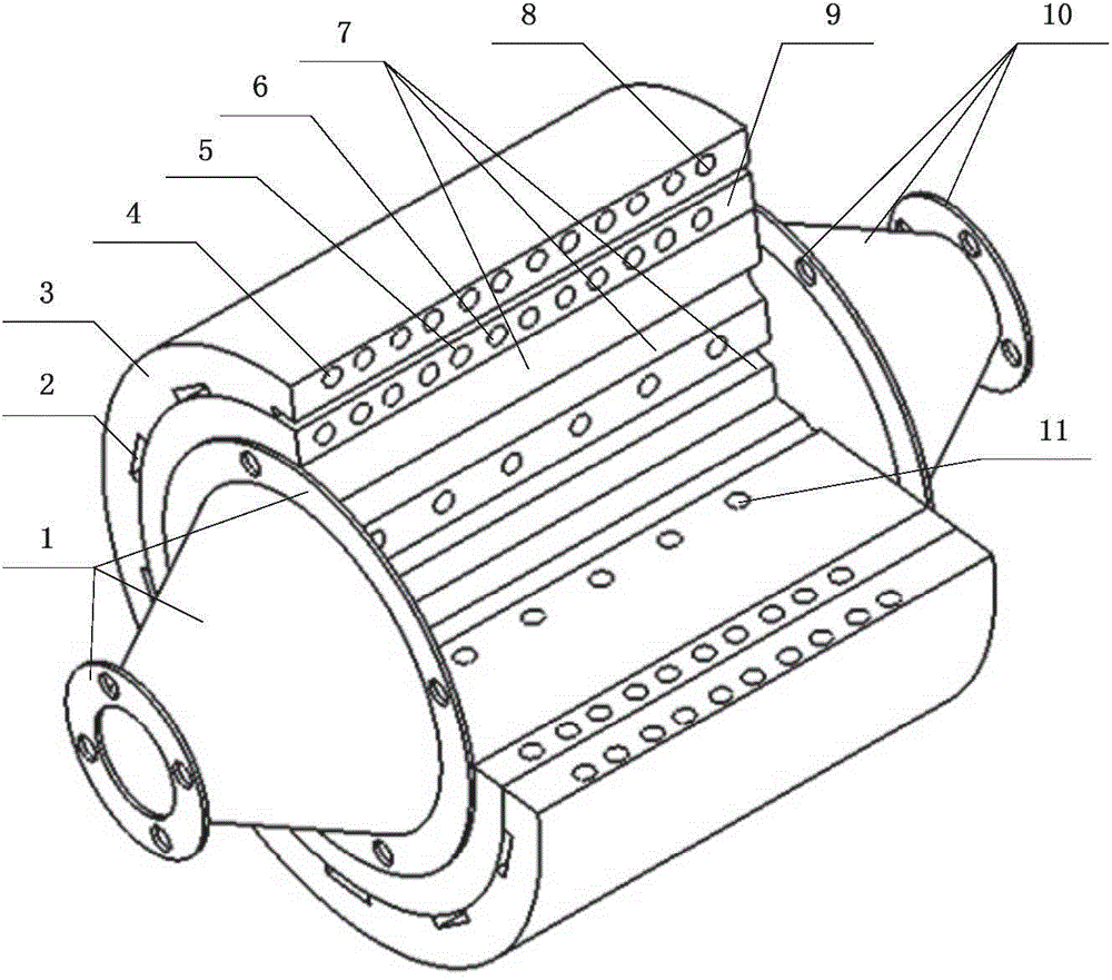
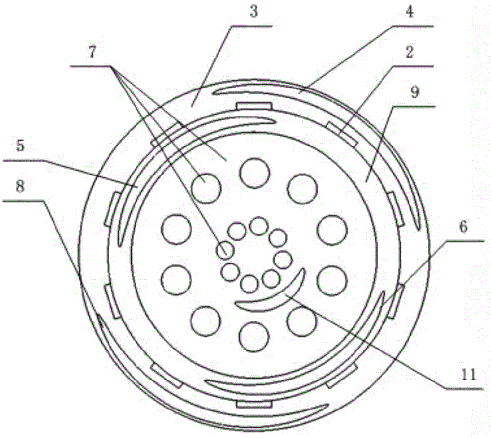
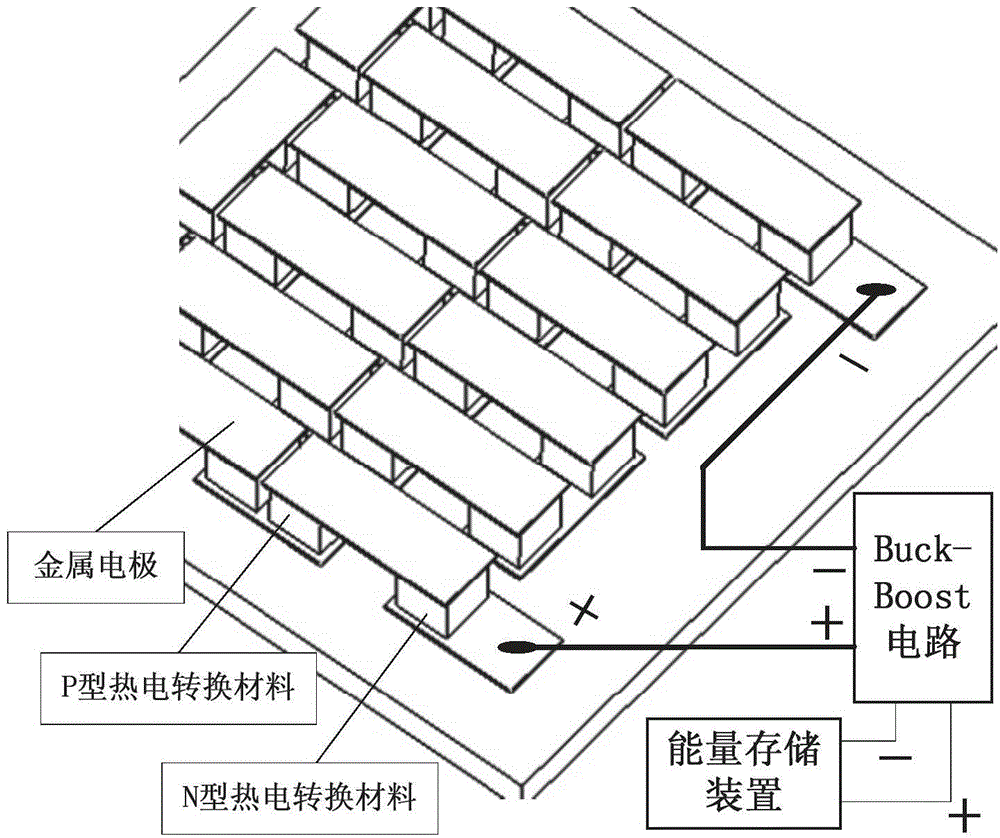
[0028] The waste heat power generation device of the honeycomb cylinder type automobile engine of the present invention comprises an intake end flange connection assembly 1, a thermoelectric power generation assembly 2, a water cooling plate 3, a water cooling plate cold water pipeline A4, a water cooling plate cold water pipeline B8, and a high temperature plate for heat exchange Medium channel A5, high temperature plate heat exchange medium channel B6, honeycomb heat exchanger 7, high temperature plate 9, air outlet flange connection assembly 10, heat exchange medium circulation channel 11. The radial sections of the high-temperature plate 9 and the water-cooled plate 3 are annular with a certain thickness, and the thermoelectric power generation assembly 2 is a square power generation assembly.

[0029] The water-cooled plate 3 is closely...


PUM


Abstract

The invention discloses a cellular cylinder type vehicle engine waste heat power generator comprising an air inlet flange connection assembly, a thermoelectric generation assembly, a water cooling plate, a water cooling plate cold water pipe A, a water cooling plate cold water pipe B, a high temperature heat transfer medium channel A, a high temperature heat transfer medium channel B, a cellular heat exchanger, a high temperature plate, an air outlet flange connection assembly, and a heat transfer medium cycle channel. Waste gas generated by an engine enters the cellular cylinder type vehicle engine waste heat power generator through the air inlet flange connection assembly; partial heat in the waste gas is collected by a heat absorb coating on an inner wall of the pipe and transferred to the heat transfer medium; the heat transfer medium transfers the heat to the high temperature plate through double helix channels in the high temperature plate. One side of the thermoelectric generation assembly is tightly attached to the high temperature plate, and the other side is cooled by the water cooling plate with flowing cold water, thus generating power under a Seebeck effect.

Description

technical field [0001] The invention relates to a thermoelectric power generation device, in particular to a waste heat power generation device for an automobile engine. Background technique [0002] The exhaust gas emitted from the engine contains high heat. Traditional vehicles directly discharge this part of the exhaust gas into the atmosphere, which not only causes a waste of energy, but also increases the temperature of the atmosphere to a certain extent, causing damage to the natural climate. The paper "Research and Application Simulation of Automobile Exhaust Thermoelectric Power Generation Technology" gives the development and simulation research of automobile exhaust waste heat recovery, but the content is biased towards theory and simulation, and the relevant structure is less involved. The waste heat recovery device given in the utility model patent No. N201020101524.7 allows the high temperature end of the thermoelectric module to be directly attached to the oute...

Claims


Application Information

Patent Timeline
Patent Type & Authority Applications(China)
IPC IPC(8): H02N11/00F01N5/02
CPCF01N5/02H02N11/002Y02T10/12
Inventor 汪若尘钱金刚孟祥鹏丁仁凯孙泽宇
Owner JIANGSU UNIV
Learn More