Welded can body, welded can, method for manufacturing welded can body, and method for manufacturing welded can

A manufacturing method and technology for tank bodies, which are applied in manufacturing tools, welding equipment, roller electrode welding, etc., can solve the problems of reduced adhesiveness of resin coating, low corrosion resistance, easy penetration, etc., to improve weldability, The effect of improving corrosion resistance and reducing electrical resistance

Active Publication Date: 2015-09-23
DAINICHI CAN +1
View PDF7 Cites 1 Cited by
  • Summary
  • Abstract
  • Description
  • Claims
  • Application Information

AI Technical Summary

Problems solved by technology

[0008] In addition, when the welded part is physically polished, the chrome plating film is completely removed. Therefore, when a resin film is formed on the welded part by repair coating, repair lamination, etc., the welded part and the repair paint film, repair Decreased adhesion of resin coatings such as laminated boards
[0009] As a result, the content easily infiltrates into the welded part and does not form a chrome-plated film on the welded part. Therefore, there is a problem that the corrosion resistance when the content infiltrates into the welded part is low, and it becomes the main cause of corrosion.

Method used


Image

  • Welded can body, welded can, method for manufacturing welded can body, and method for manufacturing welded can
  • Welded can body, welded can, method for manufacturing welded can body, and method for manufacturing welded can
  • Welded can body, welded can, method for manufacturing welded can body, and method for manufacturing welded can

Examples


no. 1 approach

[0073] Below, refer to Figures 1 to 8B A first embodiment of the present invention will be described.

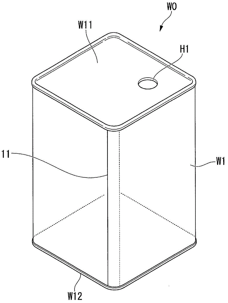
[0074] figure 1 It is a diagram showing a schematic configuration of a can body according to the first embodiment of the present invention, and symbol W0 denotes a square can such as an 18L square can (Square Can) (welded can), symbol W1 denotes a welded can body, and symbol 11 denotes a welded can body the welding part.

[0075] Such as figure 1 As shown, the rectangular can W0 includes, for example, a cylindrical can body W1, a top plate W11, and a bottom plate W12, and the top plate W11 and the bottom plate W1 are attached to openings at both ends of the welded can body W1.

[0076] A hole H1 for filling the contents into the square tank W0 or letting the contents flow out is formed in the top plate W11.

[0077] In addition, the can body W1 is joined by, for example, bending a formed material steel plate, overlapping the edges of corresponding sides, and performing ...

no. 2 approach

[0134] Below, refer to Figure 9A ~ Figure 9D A second embodiment of the present invention will be described.

[0135] Figure 9A It is a schematic diagram showing the structure of the laser irradiation part of the laser processing part G of the material steel plate used in the welded tank body of the second embodiment, Figure 9B ~ Figure 9D It is a schematic diagram explaining the modified example of 2nd Embodiment. Figure 9A ~ Figure 9D Herein, for example, the longitudinal direction of the laser processed portion G is represented by Y, and the width direction is represented by X.

[0136] The laser processing part G of the second embodiment is constituted, for example, as follows: Figure 9A As shown, a plurality of laser irradiation units 13 having a predetermined length in the Y direction are arranged in the X direction, and a plurality of laser irradiation units 13 adjacent to the X direction are arranged in a manner to be staggered by half a pitch from each other i...

no. 3 approach

[0142] Below, refer to Figure 10 A third embodiment of the present invention will be described.

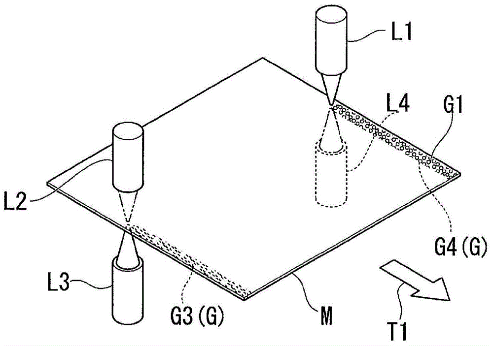
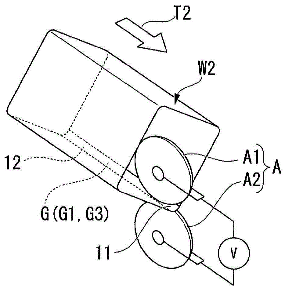
[0143] Figure 10 It is a figure explaining the schematic structure of the arrangement|positioning of the laser-processed part G on the material steel plate M at the time of seam welding the part to be welded 12 in the manufacturing process of the welded tank body of 3rd Embodiment.

[0144] The third embodiment is different from the first embodiment in that, in the first embodiment, the laser processing parts G1 and G3 are formed on both surfaces constituting the electrode contact surface of the part to be welded 12, whereas in the In the third embodiment, laser processed portions G1 and G3 are formed on both surfaces constituting the electrode contact surface.

[0145] In addition, in the third embodiment, the laser processed portions G2 and G4 are also formed on both surfaces constituting the joint surface on the interface side of the material steel sheets M to be joined, an...


PUM

PropertyMeasurementUnit
Adhesionaaaaaaaaaa

Abstract

This welded can body is constituted by forming a steel plate material formed from a tin-free steel plate or a resin coated steel plate wherein a tin-free steel plate is coated with a resin, overlapping corresponding parts with each other, and forming a weld part by resistance welding of the overlapped parts. Laser processing parts, which are formed on at least one of four surfaces made up of two surfaces constituting electrode contact surfaces on sides that make contact with an electrode (A) during the resistance welding and two surfaces constituting joining surfaces on sides where this steel plate material is joined together, have laser irradiation parts, wherein laser irradiation is carried out before the resistance welding to eliminate chrome plating and expose the steel plate, separately disposed on parts to be welded (12), which are to become the weld parts, on the steel plate material.

Description

technical field [0001] The present invention relates to an 18-liter can and an ordinary can body that can be formed by joining material steel plates composed of chrome-plated steel sheets or resin-coated steel sheets represented by laminated sheets coated with a resin coating at welded portions by resistance welding A welded can body, a welded can body, a method of manufacturing a welded can body, and a method of manufacturing a welded can improve the production efficiency of can production when welding a can. [0002] this application claims priority based on Japanese Patent Application No. 2013-014644 for which it applied to Japan on January 29, 2013, The content is used for this specification. Background technique [0003] Metal cans such as 18-liter cans and ordinary tanks are known to be manufactured by overlapping portions to be welded of material steel sheets, welding them by resistance welding such as seam welding to form a body portion, and attaching a roof plate to...

Claims


Application Information

Patent Timeline
IPC IPC(8): B23K11/08B21D51/26B23K26/351B23K26/361B65D8/16B65D8/22
CPCB65D7/06B23K11/093B21D51/26B65D7/38B65D7/045B23K11/34B23K11/08B23K11/0026B23K26/361B65D7/12B23K2101/125B23K28/02B65D1/12B23K11/066
Inventor 森冈勇治郎新井隆小林伸之久保启
Owner DAINICHI CAN
Why Eureka
Try Eureka