
Manufacture process of robot RV reducer spline eccentric shaft

An eccentric shaft and reducer technology, applied in the field of mechanical processing, can solve the problems of high processing positioning accuracy, slippage, spline eccentric shaft alignment error, etc., to improve processing accuracy and assembly accuracy, improve service life, and drive stable and reliable. Effect

Active Publication Date: 2015-09-30
GREATOO SINO GERMAN ROBOT & INTELLIGENT MFG CO LTD +1
View PDF9 Cites 7 Cited by
  • Summary
  • Abstract
  • Description
  • Claims
  • Application Information

AI Technical Summary

Problems solved by technology

The spline eccentric shaft is the core transmission part of the robot RV reducer, and is the source of power transmission of the RV reducer. The two ends of the spline eccentric shaft are equipped with tapered cylindrical bearings, and the bearing position is on the same axis as the two center holes. The CNC grinding machine can meet the machining accuracy requirements; but there are two cams in the middle, which are not on the same axis as the two top holes, and have a certain amount of eccentricity. After installing cylindrical roller bearings, they are installed on the cycloidal wheel. The positioning accuracy is high, and it is also the main part that directly affects the service life of the eccentric shaft. The machining accuracy of the processing equipment is also relatively high, which belongs to the follow-up eccentric grinding machine; It needs to be processed through multiple processes; all of the above require high processing accuracy, otherwise the spline eccentric shaft will produce alignment errors during use, which will affect the use accuracy and service life of the robot RV reducer
The end of the eccentric shaft of the transmission RV reducer is in the form of an optical shaft, and the expansion sleeve is connected with the gear as the transmission source, which will slip under the condition of large force, and will also affect the use accuracy and service life of the RV reducer.

Method used


Image

  • Manufacture process of robot RV reducer spline eccentric shaft
  • Manufacture process of robot RV reducer spline eccentric shaft
  • Manufacture process of robot RV reducer spline eccentric shaft

Examples


Embodiment Construction

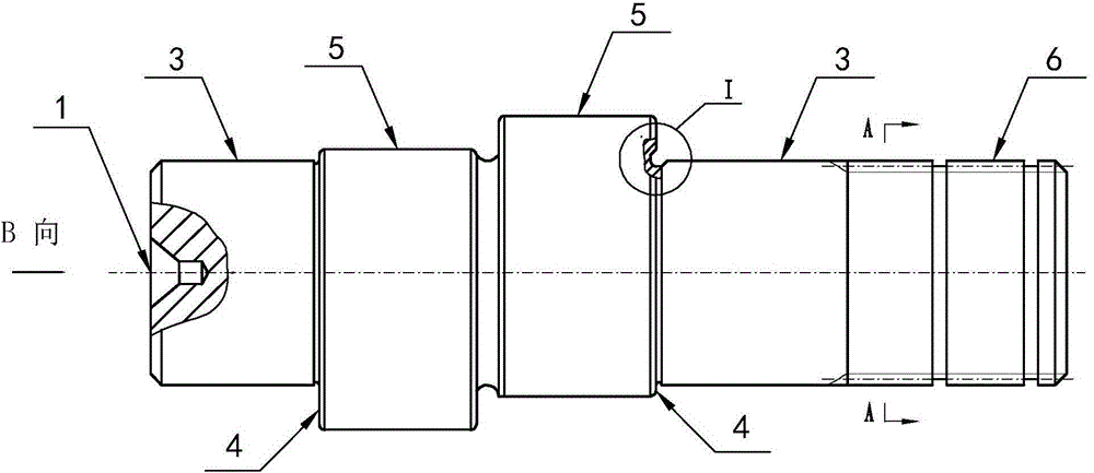
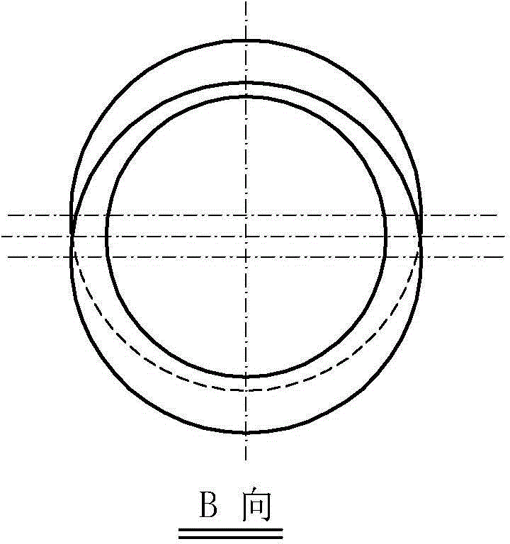
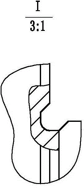
[0017] Referring to the accompanying drawings, a manufacturing process of a splined eccentric shaft of a robot RV reducer includes the following steps:

[0018] (A) Forging the spline eccentric shaft blank;

[0019] (B) Carrying out the rough turning of the spline eccentric shaft blank, drilling a center hole 1 on both ends of the spline eccentric shaft, milling a positioning groove 2 on the circumference of one end of the spline, and performing heat treatment;

[0020] (C) Use the two top holes 1 as the positioning reference to finish machining two cams 5 close to the bearing position 3 of the tapered roller bearing to ensure the dimensional tolerance between the two cam processing end faces, and at the same time use the two top holes as the positioning reference to finish machining two The cam is close to the two end faces 4 of the bearing positions of the tapered roller bearings, ensuring the bearing position of each tapered roller bearing and the dimensional tolerance betw...


PUM


Abstract

The invention discloses a manufacture process of a robot RV reducer spline eccentric shaft. The manufacture process comprises the following steps: forging a shaft blank; drilling a central tip hole in each of two end faces of the shaft blank, and milling a positioning groove in the circumference of a spline end; finish machining two cams close to the bearing positions of taper-roller bearings and finish machining two end faces of the bearing position simultaneously by adopting the two central tip holes as the positioning reference; finish grinding two end parts of the spline eccentric shaft and the bearing positions of the two taper-roller bearings by adopting the two central tip holes as the positioning reference; finish grinding the circumferential surfaces of the two cams by adopting the two central tip holes as the positioning reference; taking the two central tip holes as the reference, taking the phase difference of the two cams as a starting point to enable the phase difference of the two cams to be 180 degrees; performing gear hobbing and gear grinding on a spline by adopting the positioning groove as the reference. With adoption of the manufacture process, the processing error and the assembling error can be reduced to meet the assembling requirement of a high-precision RV reducer.

Description

technical field [0001] The invention belongs to the technical field of mechanical processing, and in particular relates to a manufacturing process of a splined eccentric shaft of a robot RV reducer. Background technique [0002] Robot RV reducer is a new kind of transmission, with small size, light weight, large transmission ratio range, long life, stable precision, high efficiency, stable transmission, strong impact resistance, large torque, high positioning accuracy, vibration A series of advantages such as small size are widely used in industrial robots, machine tools, medical testing equipment, satellite receiving systems and other fields. Its structure is complex, including support seat, planetary gear frame, two or three splined eccentric shafts, cycloidal wheel, and two or three pairs of tapered cylindrical bearings installed between the splined eccentric shaft and the planetary gear frame, installed on the flower Two or three pairs of bearings between the cam and th...

Claims


Application Information

Patent Timeline
IPC IPC(8): B23P15/00
CPCB23P15/00
Inventor 池永华吴豪蔡锐勇孙坤
Owner GREATOO SINO GERMAN ROBOT & INTELLIGENT MFG CO LTD
Learn More