Cutting tool prepared from cubic crystalline boron nitride ultrahigh pressure sintering material

A cubic crystal boron nitride, boron nitride-based technology, applied in the direction of manufacturing tools, turning equipment, metal processing equipment, etc., can solve problems such as the inability to obtain dense and high-hardness sintered bodies, shortened tool life, and tool tip defects

Active Publication Date: 2015-09-30
MITSUBISHI MATERIALS CORP
View PDF9 Cites 4 Cited by
  • Summary
  • Abstract
  • Description
  • Claims
  • Application Information

AI Technical Summary

Problems solved by technology

[0010] For example, in Patent Document 1, the cBN content can be set to 80vol%, but if the cBN content increases, the ratio of the cBN particles in contact with each other increases, and the contact portion between the cBN particles does not have a binding phase that has the effect of retaining the cBN particles. The strength of the cutting edge decreases, and when used under high-load cutting conditions, there is a problem that the cutting edge is prone to chipping and the tool life is shortened
[0011] In addition, in the cBN tool described in Patent Document 2, if the cBN content exceeds 70 vol%, the densification of the binder phase forming the continuous network is hindered, and a dense and high-hardness sintered body cannot be obtained. Moreover, if the sintering pressure exceeds 2.0 GPa, the The toughness and strength of the sintered body show a downward trend, so when used as a cBN tool, there is a problem of shortened life
[0012] In addition, in Patent Document 3, the binder phase is continuous when viewed two-dimensionally, but when the cBN content increases, the proportion of cBN particles in contact increases, and the strength of the cutting edge decreases in the contact portion between the cBN particles, and the cutting edge is prone to occur. The same problem as the cBN tool described in Citation 1 where defects occur

Method used


Image

  • Cutting tool prepared from cubic crystalline boron nitride ultrahigh pressure sintering material
  • Cutting tool prepared from cubic crystalline boron nitride ultrahigh pressure sintering material
  • Cutting tool prepared from cubic crystalline boron nitride ultrahigh pressure sintering material

Examples


Embodiment 1

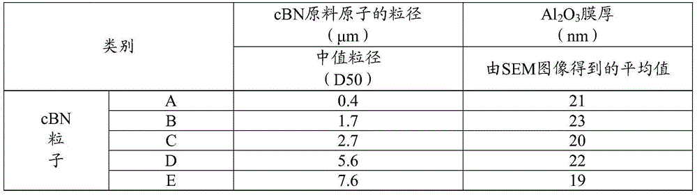
[0052] Al 2 o 3 Fabrication of film-coated cBN particle powders:

[0053] Using cBN particles having a median diameter (D50) shown in Table 1 as a substrate, the cBN particles were coated with Al having an average film thickness shown in Table 1 by the ALD (Atomic Layer Deposition) method. 2 o 3 membrane. More specifically, cBN particles having a median diameter (D50) shown in Table 1 were loaded into the furnace, and the temperature in the furnace was raised to 350°C, using Al(CH 3 ) 3 gas as film-forming gas, and H 2 O gas is used as the reaction gas, and the following (1) to (4) are regarded as one cycle, and this cycle is repeated until the target film thickness is reached, thereby forming Al with a predetermined film thickness on the surface of cBN particles. 2 o 3 membrane.

[0054] (1)Ar+Al(CH 3 ) 3 Gas inflow process

[0055] (2) Ar gas purging process

[0056] (3)Ar+H 2 O gas inflow process

[0057] (4) Ar gas purging process

[0058] In addition, for A...


PUM


Abstract

The invention provides a cutting tool prepared from a cubic crystalline boron nitride ultrahigh pressure sintering material, and the cutting tool exhibits excellent defect resistance in steel and cast-iron cutting. The cutting tool prepared from the cubic crystalline boron nitride ultrahigh pressure sintering material comprises, by volume, 50-85%, preferably 70-85%, of cubic crystalline boron nitride particles, with the balance mainly being aluminum oxide. When the detection is carried out on the cross section of the cubic crystalline boron nitride ultrahigh pressure sintering material, the total area of cubic crystalline boron nitride particles swarms accounts for higher than 10% and lower than 35% of the total area of the cubic crystalline boron nitride particles, the area of the cubic crystalline boron nitride particles swarms is larger more than 2.5 times of the average area of the cubic crystalline boron nitride particles, and the average area can be obtained through the calculation on the average particle size of the cubic crystalline boron nitride particles, so that the defect resistance is improved.

Description

technical field [0001] The present invention relates to a cutting tool made of cubic boron nitride (hereinafter referred to as cBN)-based ultra-high pressure sintered material (hereinafter referred to as cBN tool) excellent in chip resistance. Background technique [0002] Conventionally, there are known cBN tools that use a cBN-based ultra-high pressure sintered material (hereinafter, sometimes referred to as "cBN sintered body") as an affinity with the workpiece in cutting processing of iron-based workpieces such as steel and cast iron. Less compatible tool materials. [0003] For example, as shown in Patent Document 1, there is known a cBN tool in which Al 2 o 3 or Al 2 o 3 It is mainly composed of carbides and nitrides, and the thermal shock properties are improved by setting the cBN content in the range of 20 to 80 vol%. [0004] Furthermore, as shown in Patent Document 2, there is known a cBN tool in which the binder phase of a cBN sintered body contains Al 2 o ...

Claims


Application Information

Patent Timeline
Patent Type & Authority Applications(China)
IPC IPC(8): B23P15/28C04B35/5831
CPCB23B27/14C04B35/5831
Inventor 矢野雅大宫下庸介大桥忠一
Owner MITSUBISHI MATERIALS CORP
Why Eureka
Try Eureka