An ultra-low emission absorption tower

An absorption tower and ultra-low technology, applied in the field of absorption towers, can solve the problems of not meeting ultra-low emission requirements, low dust removal efficiency of absorption towers, and excessive dust emission concentration, etc., to increase spray coverage, facilitate installation, reduce Effects of Repair and Replacement Costs

Active Publication Date: 2017-06-23
CHINA HUADIAN ENG +1
View PDF3 Cites 0 Cited by
  • Summary
  • Abstract
  • Description
  • Claims
  • Application Information

AI Technical Summary

Problems solved by technology

This will easily lead to: on the one hand, the pressure loss at the side wall is relatively large; on the other hand, due to the spray arrangement structure, the concentration of the slurry near the tower wall is not as high as that in the center of the tower, which is not conducive to the SO in the flue gas. 2 and dust removal
[0006] Since the flue gas has been treated by dust removal and environmental protection facilities such as electrostatic precipitators or bag filters before entering the absorption tower, the particle size of the dust particles entering the absorption tower is mostly below 20 μm, and the particle size of the fine dust is small, resulting in low dust removal efficiency of the absorption tower, which cannot meet the requirements. 5mg / Nm for ultra-low emission requirements 3 emission requirements
Moreover, a demister flushing system is installed on the top of the absorption tower. The demister flushing system is flushed at least once every 8 hours, and the flushing time is more than 30 minutes. The emission concentration of fine dust seriously exceeds the standard in some periods

Method used


Image

  • An ultra-low emission absorption tower
  • An ultra-low emission absorption tower
  • An ultra-low emission absorption tower

Examples


Embodiment 1

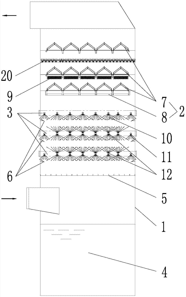
[0035] Embodiment 1 of the present invention: such as figure 1 As shown, an ultra-low emission absorption tower includes an absorption tower body 1, a mist eliminator 2, a spray layer 3, and a slurry tank 4. The slurry tank 4 is located at the bottom of the absorption tower body 1, and the mist eliminator 2 is located In the upper part of the absorption tower body 1, the spray layer 3 is arranged below the mist eliminator 2, and the lowermost spray layer 3 is provided with a slurry distribution plate 5; each spray layer 3 is provided with a slurry diversion Ring 6; Demister 2 is composed of three sets of roof-type mist eliminators 7 and a set of tube-type mist eliminators 8. The tube-type mist eliminators 8 are located under the lowest roof-type mist eliminators 7, and the lowest roof-type mist eliminators A condensation system 9 is provided between the mist eliminator 7 and the roof-type mist eliminator 7 in the middle layer. The spraying layer 3 has more than two layers, and ...

Embodiment 2

[0040] Embodiment 2 of the present invention: such as figure 1 As shown, an ultra-low emission absorption tower includes an absorption tower body 1, a mist eliminator 2, a spray layer 3, and a slurry tank 4. The slurry tank 4 is located at the bottom of the absorption tower body 1, and the mist eliminator 2 is located In the upper part of the absorption tower body 1, the spray layer 3 is arranged below the mist eliminator 2, and the lowermost spray layer 3 is provided with a slurry distribution plate 5; each spray layer 3 is provided with a slurry diversion Ring 6; Demister 2 is composed of three sets of roof-type mist eliminators 7 and a set of tube-type mist eliminators 8. The tube-type mist eliminators 8 are located under the lowest roof-type mist eliminators 7, and the lowest roof-type mist eliminators A condensation system 9 is provided between the mist eliminator 7 and the roof-type mist eliminator 7 in the middle layer. The spraying layer 3 has more than two layers, and ...

Embodiment 3

[0045] Embodiment 3 of the present invention: figure 1 As shown, an ultra-low emission absorption tower includes an absorption tower body 1, a mist eliminator 2, a spray layer 3, and a slurry tank 4. The slurry tank 4 is located at the bottom of the absorption tower body 1, and the mist eliminator 2 is located In the upper part of the absorption tower body 1, the spray layer 3 is arranged below the mist eliminator 2, and the lowermost spray layer 3 is provided with a slurry distribution plate 5; each spray layer 3 is provided with a slurry diversion Ring 6; Demister 2 is composed of three sets of roof-type mist eliminators 7 and a set of tube-type mist eliminators 8. The tube-type mist eliminators 8 are located under the lowest roof-type mist eliminators 7, and the lowest roof-type mist eliminators A condensation system 9 is provided between the mist eliminator 7 and the roof-type mist eliminator 7 in the middle layer. The spraying layer 3 has more than two layers, and the uppe...


PUM

PropertyMeasurementUnit
dust removal efficiencyaaaaaaaaaa

Abstract

The invention discloses an ultra-low emission absorption tower, which comprises an absorption tower body, a mist eliminator, a spray layer and a slurry pool, the slurry pool is arranged at the bottom of the absorption tower body, and the mist eliminator is arranged at the upper part of the absorption tower body , the spray layer is set under the demister, the bottom of the lowest spray layer is provided with a slurry distribution plate; the bottom of each spray layer is equipped with a slurry guide ring; the demister is composed of three sets of roof-type defogging It consists of a demister and a set of tube type demisters. The tube type demisters are located below the ridge type demisters on the lowest level, and there is a condensation and system. The invention can remove fine dust with small particle size in the flue gas of the power plant, effectively increase the spray coverage, and increase the SO in the flue gas. 2 It can effectively prevent the wear of the inner wall of the absorption tower body, and at the same time guide the flue gas to make the flue gas flow to the spray intensive area and reduce the pressure loss at the side wall.

Description

Technical field [0001] The invention relates to an absorption tower, particularly an ultra-low emission absorption tower, which belongs to the field of environmental protection. Background technique [0002] The absorption tower is mainly used for flue gas desulfurization in coal-fired power plants and equipment to assist dust removal. The absorption slurry is sprayed from top to bottom, and the flue gas flows from bottom to top in the absorption tower to remove SO in the flue gas 2 And dust. [0003] The selection and arrangement of nozzles on the spray layer directly affect the SO in the flue gas 2 In addition to the dust removal effect, most of the existing absorption towers use one-way nozzles, and the spray coverage rate is low. Because the flue gas is unevenly distributed after the flue gas enters the absorption tower, the phenomenon of local flue gas escape will occur. [0004] The absorption tower absorbs the slurry and sprays from top to bottom. The nozzle on the outermost ...

Claims


Application Information

Patent Timeline
Patent Type & Authority Patents(China)
IPC IPC(8): B01D53/18B01D47/06
Inventor 金颖姗李苇林陶爱平吴冲汪洋赵冰王凯亮沈煜晖
Owner CHINA HUADIAN ENG
Why Eureka
Try Eureka