A beating equipment for toilet paper machine

A technology for toilet paper and equipment, applied in the field of beating equipment of toilet paper machines, can solve the problems of not the best quality of finished products, affecting the quality of finished paper, unfavorable mixed feeding, etc., to improve the quality and improve the method, category and structure of feeding. simple effect

Active Publication Date: 2017-08-11
江苏富星纸业有限公司
View PDF5 Cites 1 Cited by
  • Summary
  • Abstract
  • Description
  • Claims
  • Application Information

AI Technical Summary

Problems solved by technology

[0002] At present, most of the beaters on the market are hard cardboard or paper product beaters. This kind of beater is generally a flying knife roller (equipped with a metal blade), and a fixed bottom knife is installed under it, and the pulp circulates in the tank. , Through the action between the flying knife and the bottom knife, some phenomena such as transverse cutting and longitudinal splitting are produced, so as to make paper that meets the hardness. Such a beater cannot be used as toilet paper because of the mutual beating of the flying knife and the bed knife. Beating. At the same time, the general beating machine has a single feeding port. Although such a feeding port can be used for convenient and fast feeding, it is not conducive to mixed feeding. If mixing is required, two kinds of mixed materials cannot be put in at the same time. The quality of the final product must not be the best, and there is no filtering equipment. Usually, there are residues mixed in the finished product. At the same time, due to the large amount of water and heat generated during the beating process, it needs to be evaporated. If it is caused by external influences, Evaporation is unfavorable and even affects the quality of finished paper

Method used


Image

  • A beating equipment for toilet paper machine
  • A beating equipment for toilet paper machine

Examples


Embodiment Construction

[0014] The following will clearly and completely describe the technical solutions in the embodiments of the present invention with reference to the accompanying drawings in the embodiments of the present invention. Obviously, the described embodiments are only some, not all, embodiments of the present invention. Based on the embodiments of the present invention, all other embodiments obtained by persons of ordinary skill in the art without making creative efforts belong to the protection scope of the present invention.

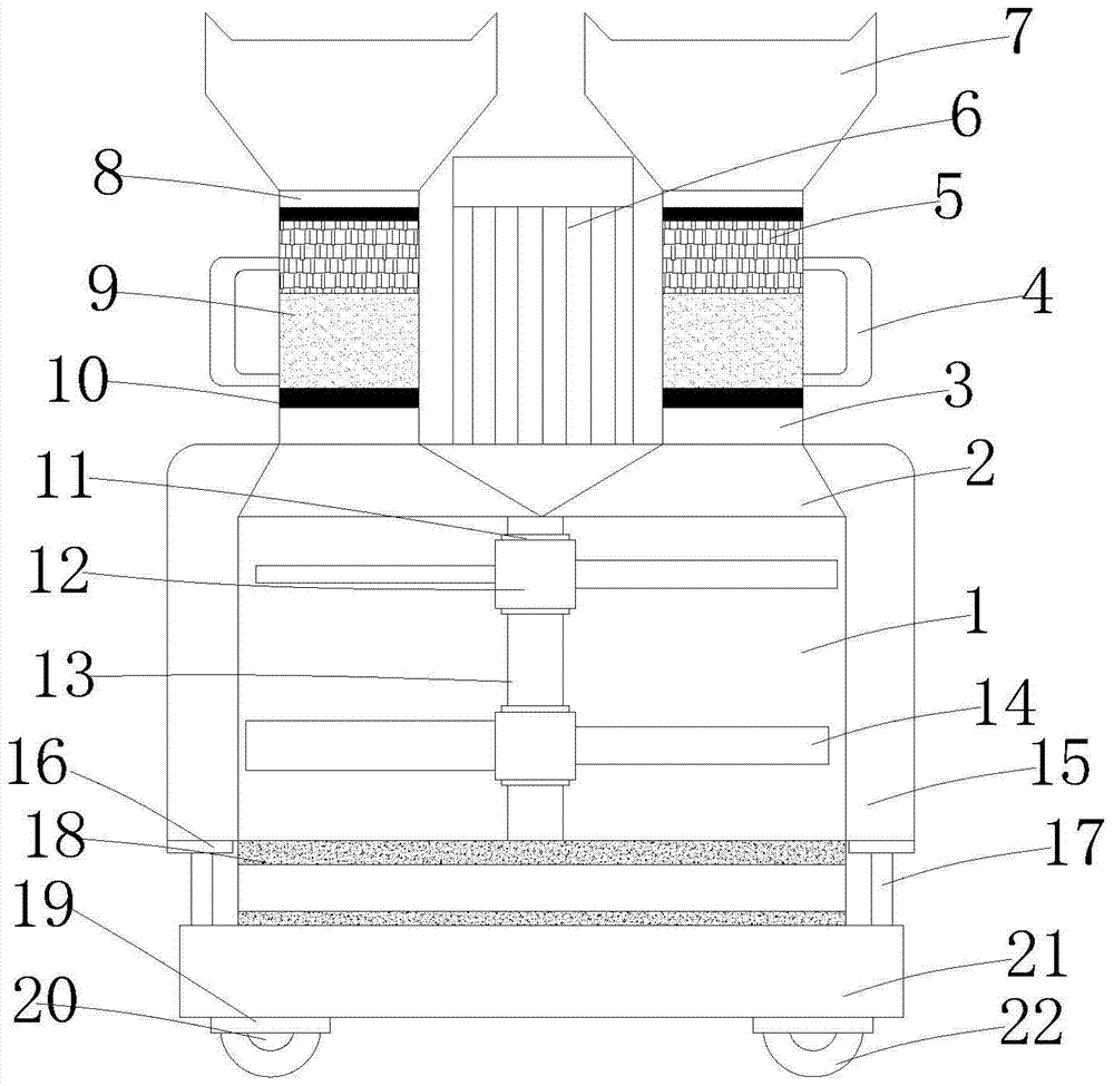
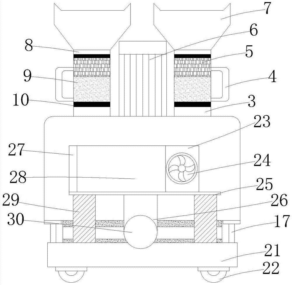
[0015] see Figure 1-2 , the present invention provides a technical solution: a beating equipment for a tissue machine, comprising a beating box 1, a main shaft 13 and an exhaust fan 23, the left and right sides of the top of the beating box 1 are connected with a paddle opening 2, and the paddle opening The top of the paddle 2 is connected with the paddle inlet channel 3, and the inner cavity of the paddle inlet channel 3 is provided with a filter tank 10, an...


PUM


Abstract

The invention discloses beating equipment for a toilet paper machine. The beating equipment for the toilet paper machine comprises a beating box, a main shaft and an exhaust fan, the left side and the right side of the top of the beating box are connected with pulp dividing openings, the tops of the pulp dividing openings are connected with pulp inlet channels, the tops of the pulp inlet channels are fixedly provided with feeding openings through fixed rings, the outer ring of the main shaft is sleeved with a paddle seat, and paddles are welded to the outer side of the paddle seat. The beating equipment for the toilet paper machine is simple in structure and convenient to use, double-tube feeding is adopted, on the one hand, the double-tube feeding speed is not lower than single-tube feeding speed, on the other hand, convenience is provided for multiple special mixing modes and feeding modes at the same time, the feeding modes and categories are effectively improved, the exhaust fan is arranged at the same time, water mist and heat can be effectively pulled out, the quality of finished paper is improved, it is effectively guaranteed that work is carried out smoothly, and meanwhile the quality of the pulp is greatly improved.

Description

technical field [0001] The invention relates to the technical field of beating machines, in particular to beating equipment for toilet paper machines. Background technique [0002] At present, most of the beaters on the market are hard cardboard or paper product beaters. This kind of beater is generally a flying knife roller (equipped with a metal blade), and a fixed bottom knife is installed under it, and the pulp circulates in the tank. , Through the action between the flying knife and the bottom knife, some phenomena such as transverse cutting and longitudinal splitting are produced, so as to make paper that meets the hardness. Such a beater cannot be used as toilet paper because of the mutual beating of the flying knife and the bed knife. Beating. At the same time, the general beating machine has a single feeding port. Although such a feeding port can be used for convenient and fast feeding, it is not conducive to mixed feeding. If mixing is required, two kinds of mixed ...

Claims


Application Information

Patent Timeline
Patent Type & Authority Patents(China)
IPC IPC(8): D21D1/02
CPCD21D1/02
Inventor 徐先平
Owner 江苏富星纸业有限公司
Why Eureka
Try Eureka