Guidance flying object damping loop structure rotation verification platform

A loop structure and verification platform technology, which is applied in the testing of machines/structural components, measuring devices, instruments, etc., can solve problems such as damping loop structure verification or lack of testing technology, shorten test time and complexity, and ensure safe operation , High stability effect

Active Publication Date: 2017-12-01
SHANGHAI CAMA OPTOELECTRONICS EQUIP
View PDF2 Cites 0 Cited by
  • Summary
  • Abstract
  • Description
  • Claims
  • Application Information

AI Technical Summary

Problems solved by technology

Even so, there is a severe lack of verification or testing techniques for the relevant damping loop structures

Method used


Image

  • Guidance flying object damping loop structure rotation verification platform
  • Guidance flying object damping loop structure rotation verification platform
  • Guidance flying object damping loop structure rotation verification platform

Examples


Embodiment 1

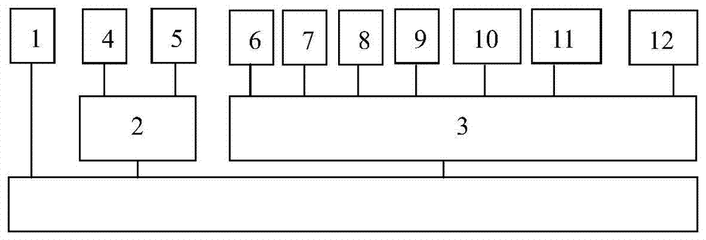
[0032] Embodiment 1: as attached figure 1 As shown in or 2, the power supply 6, product testing device 7, turntable control module 8, support control module 9, combined force decomposition module 10, data acquisition and analysis module 11 and industrial computer 12 in the product comprehensive test system 3 are collectively installed in the same control cabinet inside the device.

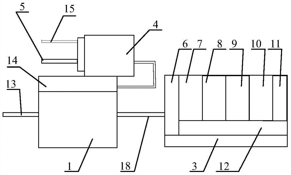
[0033] In the foregoing, the turntable mechanism 1 and the rotating bracket 4 are clamping and supporting devices for the tested product, and the tested product 19 is clamped on the rotating bracket 4 to realize motion and posture simulation.

[0034] In the foregoing, the main shaft of the turntable mechanism 1 and the main shaft of the rotating support 4 are both hollow structures, leaving a reasonable space for the arrangement of the gas supply pipeline.

[0035] In the above, in order to ensure the safety and reliability of the damping circuit design verification platform, the rotating bracket...

Embodiment 2

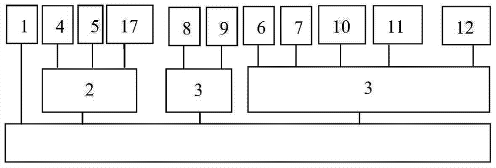
[0036] Embodiment 2: as attached image 3 , 4 Or as shown in 5, a rudder moment loading device 5 and a reference rudder deviation signal acquisition device 17 are installed at the front of the rotating bracket 4; the control part equipment of the product comprehensive testing system 3 is respectively installed on two mutually independent control cabinets, wherein the turntable control module 8 and the bracket control module 9 are installed on the industrial computer of the first control cabinet; the power supply 6, the product testing device 7, the combined force decomposition module 10, the data acquisition and analysis module 11, and the industrial computer 12 are installed on the second control cabinet.

[0037] In the foregoing, a power supply 6, an industrial computer 12 and a driver 25 are installed on the first control cabinet where the turntable control module 8 and the support control module 9 are installed, wherein a program-controlled processor 26 is installed on th...


PUM


Abstract

The rotating verification platform for the damping circuit structure of the guided flying object is composed of four parts: the turntable mechanism (1), the rotating support device (2), the air supply system and the control system. The loading device (5), while the center of the rotating bracket (4) is connected to the compressed air branch pipe (15) through a high-pressure rotating air ring, the main shaft of the turntable mechanism (1) and the rotating support device (2) is a hollow structure, and its hollow cavity is respectively connected with the supply The gas system is connected; the turntable mechanism (1) and the rotating support device (2) are connected to the control system through the test cable (18); it can simulate the counterclockwise rotation state of the flying object against the course, the test accuracy can reach 1%, and the operation is more intelligent and convenient; Each module has a high degree of integration. It can accurately measure the effective value, peak value and corresponding waveform curve of the damping circuit of the product under test, judge the state of the damping circuit, and ensure the safe operation of the equipment.

Description

technical field [0001] The invention relates to an auxiliary inspection technology for a damping loop structure, and belongs to the technical field of IPC international classification G01R measuring electric variables or magnetic variables, in particular to a rotating verification platform for a damping loop structure of a guided flying object. Background technique [0002] In the daily preventive test program, the damping circuit verification test is very important. For example, in the field of power transmission and transformation, the failure of the electromagnetic damping circuit causes the number of capacitive voltage transformers out of operation to account for more than 60% of the total number of failures. Due to the inability to accurately carry out the state analysis of the damping circuit, the electromagnetic part of the capacitive voltage transformer frequently suffers from heat generation, abnormal secondary voltage, and even bursting of the low-voltage fuse, whi...

Claims


Application Information

Patent Timeline
Patent Type & Authority Patents(China)
IPC IPC(8): G01M13/00
Inventor 李康刁海南
Owner SHANGHAI CAMA OPTOELECTRONICS EQUIP
Why Eureka
Try Eureka