Over-temperature protection circuit

An over-temperature protection circuit and circuit technology, which is applied to emergency protection circuit devices, circuit devices, emergency protection devices for automatic disconnection, etc., can solve problems such as large layout area, low output accuracy, and complex circuit structure of hysteresis comparators , to achieve the effect of preventing thermal oscillation, high output accuracy and flexible setting

Active Publication Date: 2015-10-07
UNIV OF ELECTRONIC SCI & TECH OF CHINA
View PDF2 Cites 11 Cited by
  • Summary
  • Abstract
  • Description
  • Claims
  • Application Information

AI Technical Summary

Problems solved by technology

[0006] In order to solve the defects of traditional over-temperature protection schemes such as complex circuit structure, low output accuracy, hysteresis comparator and large layou

Method used


Image

  • Over-temperature protection circuit
  • Over-temperature protection circuit
  • Over-temperature protection circuit

Examples


Embodiment 1

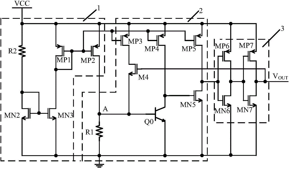
[0025] Such as image 3 As shown, an over-temperature protection circuit includes: a constant current generating circuit 1, an output control circuit 2, and an output shaping circuit 3, wherein,

[0026] The constant current generating circuit 1 includes: a second resistor R2, a second NMOS transistor MN2, a third NMOS transistor MN3, a first PMOS transistor MP1 and a second PMOS transistor MP2, wherein one end of the second resistor R2 is connected to the power supply voltage VCC, and the second The gate of the second NMOS transistor MN2 is connected to the drain, and is connected to the other end of the second resistor R2 and the gate of the third NMOS transistor MN3, and the gate of the first PMOS transistor MP1 is connected to the drain, and is connected to the second PMOS transistor MN3. The gate of the transistor MP2 is connected, the drain of the first PMOS transistor MP1 is connected to the drain of the third NMOS transistor MN3, the sources of the first PMOS transisto...

Embodiment 2

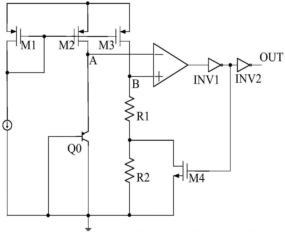
[0043] In embodiment 2 of the present invention, such as Figure 4 As shown, the working principle of the above over-temperature protection circuit is as follows:

[0044] The working principle of this example is similar to that of Example 1, the difference is that the hysteresis control tube M4 in Example 1 is replaced by a PMOS tube by an NMOS tube, and the gates of the PMOS tubes are respectively connected to the gates of the sixth NMOS tube and the sixth PMOS tube. The drains are connected, the source is connected with the drain of the third PMOS transistor, and the drain is connected with the base of the Q0 transistor.

[0045] When the die temperature falls below the thermal shutdown temperature threshold point T 0 At this time, the over-temperature protection outputs a low level, at this time the gate voltage of the M4 tube is high, and the M4 tube is cut off. When the temperature exceeds the thermal shutdown temperature threshold point T 0 At this time, the over-temp...


PUM


Abstract

The invention discloses an over-temperature protection circuit. The over-temperature protection circuit comprises a constant current generation circuit, an output control circuit, and an output shaping circuit. An NPN transistor Q0 is employed as a control switch tube. A hysteresis control tube M4 can be employed as an NMOS tube and also can be employed as a PMOS tube. Temperature hysteresis is achieved through introduction of an extra current after over-temperature and a hysteresis temperature magnitude can be arranged through adjustment of a ratio of width to length of an M4 tube. The over-temperature protection circuit is simple in structure, does not need any high-precision voltage comparators, the used device number is low, the output precision is high, a turn-off signal can be generated at a thermal turn-off temperature threshold point accurately, debugging is convenient, the over-temperature protection circuit has a temperature hysteresis function, the hysteresis temperature can be arranged flexibly, heat oscillation phenomena are prevented, and the over-temperature protection circuit is suitable for usage of chips of a power supply and a driving circuit and the like.

Description

technical field [0001] The invention relates to an over-temperature protection circuit used in electronic circuits, which is suitable for the field of analog integrated circuits. Background technique [0002] With the continuous development of integrated circuit technology, the integration of integrated circuits is increasing, the number of components integrated on a single chip is increasing, the power consumption of the chip is increasing, and the local temperature of the chip is rising too fast and too high The temperature of the chip will seriously affect the performance and reliability of the chip, and even cause permanent damage to the chip. [0003] In order to avoid damage to the chip caused by excessive temperature, an over-temperature protection circuit is generally introduced into the chip. When the chip temperature reaches a certain value, the chip will stop working and the chip will cool down. [0004] figure 1 It is a traditional over-temperature protection c...

Claims


Application Information

Patent Timeline
IPC IPC(8): H02H5/04
Inventor 乔明陈钢李妍月李阳张波
Owner UNIV OF ELECTRONIC SCI & TECH OF CHINA
Why Eureka
Try Eureka