Optical system image quality compensating apparatus

A technology of optical system and compensation device, which is applied in the direction of optics, photo-plate making process exposure device, optical components, etc., can solve the problems of difficult assembly, difficult adjustment, and high requirements for device sealing, and achieves convenient operation, low assembly difficulty, and excellent structure simple effect

Active Publication Date: 2015-10-14
SHANGHAI MICRO ELECTRONICS EQUIP (GRP) CO LTD
View PDF4 Cites 13 Cited by
  • Summary
  • Abstract
  • Description
  • Claims
  • Application Information

AI Technical Summary

Problems solved by technology

However, the hydraulic method of the device is difficult to realize and requires high sealing of the device, otherwise it is easy to contaminate the optical components, the overall structure is complex, the assembly is difficult, and it is not easy to adjust

Method used


Image

  • Optical system image quality compensating apparatus
  • Optical system image quality compensating apparatus
  • Optical system image quality compensating apparatus

Examples


Embodiment Construction

[0022] Specific embodiments of the present invention will be described in detail below in conjunction with the accompanying drawings.

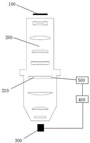
[0023] Such as figure 1 as shown, figure 1 It is a structural schematic diagram of the exposure device of the present invention. The exposure device mainly includes a reticle 100 , an optical system 200 , a fine mechanism control unit 500 , a main control system 400 and a wavefront sensor 300 . The micro-mechanical control unit 500 controls the deformable mirror 210 , and the micro-mechanical control unit 500 is connected with the main control system 400 . The wavefront sensor 300 detects the image quality of the incident light for imaging, and feeds back the obtained image quality to the main control system 400. The main control system 400 determines the compensation amount by analyzing the deviation between the image quality of the incident light for imaging and the expected image quality, The change of the surface shape of the deformable...


PUM


Abstract

The invention provides an optical system image quality compensating apparatus which comprises a distorting lens and a plurality of micro mechanisms. The apparatus is characterized in that optical system image quality compensation is realized by means of the micro mechanisms changing local face types of the distorting lens or adjusting the positions of a micromotion lens along a Z direction or theta X, theta Y directions. The optical system image quality compensating apparatus provided in the invention has the advantages of simple structure, lowered assembling difficulties, stability, reliability and convenient operation.

Description

technical field [0001] The invention relates to the technical field of semiconductor manufacturing, and further relates to an image quality compensation device for an optical system of a lithography machine. Background technique [0002] With the continuous development of the semiconductor industry, the requirements for lithography machines are getting higher and higher, and the requirements for the image quality of the projection optical system are also getting higher and higher. Environmental factors, processing errors of optical components and other factors bring high The step image has become a technical problem in the realization of indicators. However, the high-order image quality brought about by various factors cannot be compensated by adjusting the movable lens, especially for high-order asymmetric image quality. In order to solve such problems, a device capable of realizing correction and compensation of high-order asymmetric image quality is required. [0003] A...

Claims


Application Information

Patent Timeline
Patent Type & Authority Applications(China)
IPC IPC(8): G02B26/02G02B26/08G03F7/20
Inventor 汪明天马很很
Owner SHANGHAI MICRO ELECTRONICS EQUIP (GRP) CO LTD
Why Eureka
Try Eureka