Eureka AIR delivers breakthrough ideas for toughest innovation challenges, trusted by R&D personnel around the world.

An output overvoltage protection circuit

A technology to protect circuits and output overvoltage, which is applied in the direction of emergency protection circuit devices, electrical components, and measurement of electrical variables. It can solve problems such as high circuit requirements, inaccurate voltage division ratios, and inaccurate voltage values, and reduce circuit complexity. The effect of reducing the speed requirement and accurate pressure division

Active Publication Date: 2017-09-29
SHANGHAI ORIENT CHIP TECH CO LTD
View PDF5 Cites 2 Cited by
  • Summary
  • Abstract
  • Description
  • Claims
  • Application Information

AI Technical Summary

Problems solved by technology

In order to ensure lower power consumption of the voltage divider circuit, the voltage divider resistor R2 is very large, usually reaching hundreds of k to several M ohms. The above resistance and parasitic capacitance will cause a certain delay in the detection voltage SWS1 compared to SW, and the resistance and capacitance values The larger the , the longer the delay time; and the current development trend of DC-DC circuits is that the switching frequency is getting higher and higher, and the output overvoltage usually occurs under the condition of high duty cycle, that is, the detection time at this time is very short , therefore, the above situation will cause the detected voltage value to be inaccurate or even unable to detect the exact value of the voltage of the switching node SW
The waveform in Figure 4(b) illustrates this situation. It can be seen from the figure that the actual detected voltage is greatly different from the expected voltage due to the influence of parasitic effects
At the same time, the voltage of SWS1 point changes rapidly, which requires a high speed of the comparator, and the comparator needs to quickly respond to the voltage change of SWS1 point, which increases the difficulty of circuit design.
For example, the patent document CN101212134A uses diode reverse breakdown voltage as the detection condition, but its voltage divider circuit contains both diodes and resistors, so the voltage division ratio will be inaccurate, and SW is detected every switching cycle in this scheme. A fast comparator is required, so the circuit is demanding
Therefore, this detection method is difficult to detect, and requires a fast and accurate detection circuit and a fast comparator, otherwise it will not be able to detect the OVP (Over Voltage Protection) state

Method used


Image

  • An output overvoltage protection circuit
  • An output overvoltage protection circuit
  • An output overvoltage protection circuit

Examples


Embodiment Construction

[0026] Below in conjunction with the drawings, preferred embodiments of the present invention are given and described in detail.

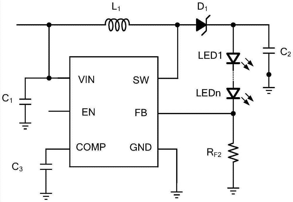
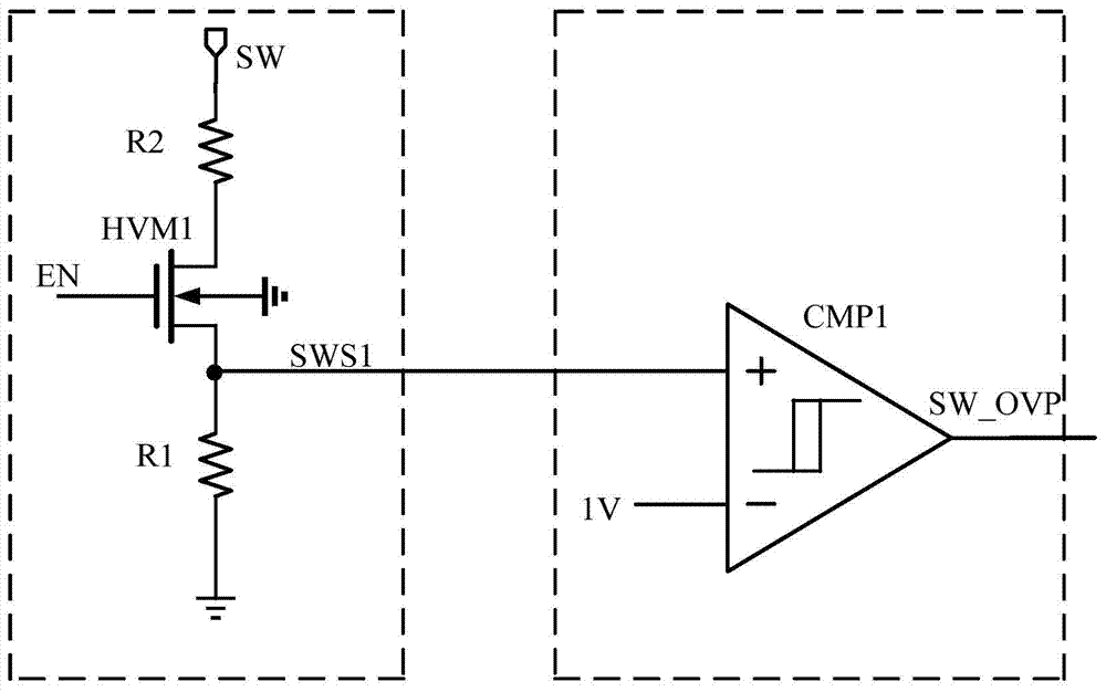
[0027] Such as Figure 5 As shown, the present invention is an output overvoltage protection circuit, which includes: a voltage detection module 1 , a sample and hold module 2 and a hysteresis comparator CMP1 .

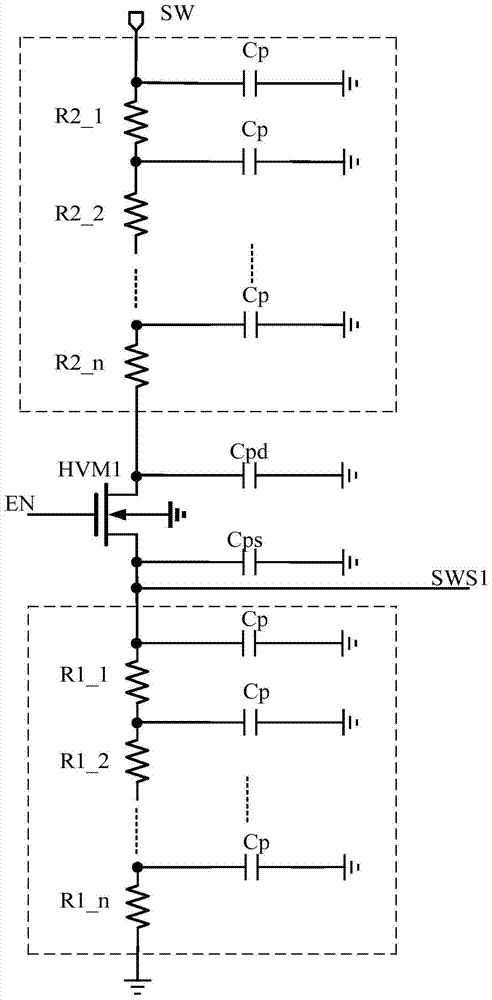
[0028] Specifically, the voltage detection module 1 includes: a first resistor R1, a second resistor R2, a high-voltage isolation transistor (which is specifically an NMOS transistor) HVM1 and a first resistor R1 connected in series between the switch node SW of the external boost chip and the ground. The three resistors R3 also include a coupling capacitor C1 connected in parallel to both ends of the second resistor R2, wherein:

[0029] The substrate of the first resistor R1 is an N well, and its substrate is connected to the switch node SW;

[0030] The substrate of the second resistor R2 is a P well, and the substrate is grounded;

...


PUM


Abstract

The present invention relates to an output overvoltage protection circuit, which includes a voltage detection module and a hysteresis comparator, wherein the voltage detection module includes: a first resistor, a second resistor, The high-voltage isolation tube and the third resistor also include a coupling capacitor connected in parallel to both ends of the second resistor; the output overvoltage protection circuit also includes a sample-and-hold connected between the voltage detection module and the hysteresis comparator module. In the present invention, the parasitic capacitance of the first resistor to the switch node offsets the parasitic capacitance of the second resistor to the ground, and at the same time, increases the coupling capacitance to offset the parasitic capacitance of the source and drain of the high-voltage isolation tube to the ground, so that the detection voltage follows the The voltage of the switch node realizes the purpose of rapidly detecting the voltage of the switch node of the boost chip.

Description

technical field [0001] The invention relates to the technical field of integrated circuit switching power supplies, in particular to an output overvoltage protection circuit for a step-up DC-DC integrated circuit. Background technique [0002] Switching power supply is widely used due to its high efficiency. Switching power supply usually needs a variety of protection functions to prevent damage caused by abnormal operation in the application. The overvoltage protection function is to prevent the chip or device from being broken down due to excessive output voltage. damage. [0003] figure 1 It is an application diagram of a typical step-up DC-DC circuit as an LED drive circuit. There are usually two methods for voltage detection of overvoltage protection: one is to directly detect the output voltage VOUT; the other is to detect the voltage of the switch node SW so that Indirect detection of VOUT voltage. [0004] For the first detection method, because the output voltage...

Claims


Application Information

Patent Timeline
Patent Type & Authority Patents(China)
IPC IPC(8): H02H7/12G01R19/165
Inventor 罗杰刘迎迎贾舒方王坚奎吴玉江
Owner SHANGHAI ORIENT CHIP TECH CO LTD
Why Eureka
Eureka Blog
Learn More