Soft-nitrided induction-quenched steel component
一种高频淬火、软氮化的技术,应用在提高能源效率、工艺效率的提高、涂层等方向,能够解决压缩残余应力小、不优选、淬火应变大等问题,达到面疲劳强度优异的效果
- Summary
- Abstract
- Description
- Claims
- Application Information
AI Technical Summary
Problems solved by technology
Method used
Image
Examples
Embodiment
[0106] Next, examples of the present invention will be described. The conditions of the examples are examples used to confirm the practicability and effects of the present invention, and the present invention is not limited to this example. In the present invention, various conditions can be adopted as long as the object of the present invention is achieved without departing from the gist of the present invention.
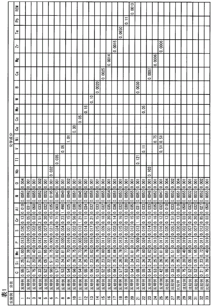
[0107] Each steel material having the chemical composition shown in Table 1 was heated to 1250° C., hot forged, left to cool to room temperature, heated again, and normalized at 850° C. for one hour. Thereafter, for use in the roller pitting fatigue test piece, a small roller test piece having a cylindrical portion with a diameter of 26 mm and a width of 28 mm and a large roller test piece with a diameter of 130 mm and a width of 18 mm were produced by machining. Furthermore, hardness and residual stress measurement test pieces having a diameter of 26 mm and a len...
Embodiment 30
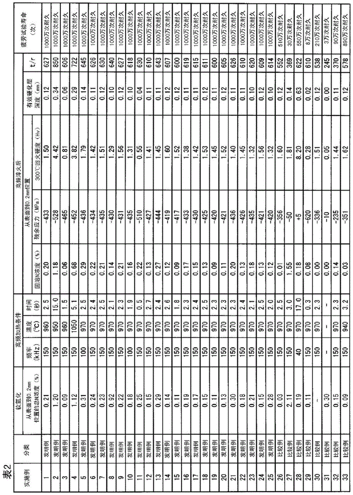
[0110] In Example 30, no nitrocarburizing treatment was performed, and only induction hardening was performed. In addition, in Example 31, only nitrocarburizing treatment was performed under the above-mentioned conditions (soft nitrocarburizing time: 2 hours), and induction hardening was not performed.
[0111]Using the fabricated large and small rollers, a roller pitting fatigue test was performed as a standard surface fatigue test. The roller pitting fatigue test is carried out as follows: set the surface pressure to the Herbschel stress of 3500 MPa to press the large roller against the small roller, so that the direction of the peripheral speed of the two rollers on the contact part is set to the same direction, and the The slip ratio was set to -40% (the peripheral speed of the contact portion of the large roller was 40% greater than that of the small roller) and it was rotated. The oil temperature of the gear oil supplied to the contact portion was set at 80°C. The serv...
Embodiment 26
[0116] Examples 26 and 27 are examples in which the concentration of solid solution N in the surface layer after induction hardening deviates from the present invention. The steel material of Example 26 is the same as that of Example 1, but the nitrocarburizing treatment time is shorter. Therefore, the concentration of solid solution N in the surface layer did not reach 0.05%, the 300°C tempering hardness of the surface layer showed a low value less than Hv600, and the life was short. The steel material of Example 27 is the same as that of Example 4, but the nitrocarburizing treatment time is long. Therefore, the concentration of solid solution N in the surface layer exceeds 1.5%, and a large amount of retained austenite exists, so the tempering hardness of the surface layer at 300°C is low, and the compressive residual stress near the surface is reduced due to the small volume change during quenching, so the life is short .
PUM
| Property | Measurement | Unit |
|---|---|---|
| depth | aaaaa | aaaaa |
| diameter | aaaaa | aaaaa |
| diameter | aaaaa | aaaaa |
Abstract
Description
Claims
Application Information
 - R&D
- Intellectual Property
- Life Sciences
- Materials
- Tech Scout
- Unparalleled Data Quality
- Higher Quality Content
- 60% Fewer Hallucinations
Browse by: Latest US Patents, China's latest patents, Technical Efficacy Thesaurus, Application Domain, Technology Topic, Popular Technical Reports.
© 2025 PatSnap. All rights reserved.Legal|Privacy policy|Modern Slavery Act Transparency Statement|Sitemap|About US| Contact US: help@patsnap.com


