Vibration ash removal type circulating fluidized bed boiler

A circulating fluidized bed and boiler technology, which is used in fluidized bed combustion equipment, removal of solid residues, and fuel burned in a molten state, etc., can solve the problem of affecting ash removal efficiency, difficult to unify the steps of heating surface tube bundles, and the effect of heating surface tube bundles. Weak strength and other problems, to achieve the effect of increasing the temperature of the endothermic working medium, reducing the temperature of the exhaust gas, and reducing wear and tear

Active Publication Date: 2015-10-21
HMEI THREAD CO LTD OF YINBIN SICHUAN +1
View PDF6 Cites 9 Cited by
  • Summary
  • Abstract
  • Description
  • Claims
  • Application Information

AI Technical Summary

Problems solved by technology

[0008] 1. The tube bundles on the heating surface are suspended vertically in the flue. The superheater, evaporator and economizer are assembled into a whole by the header, roof box, ceiling tube, serpentine tube, and rapping tube respectively, and then connected to the tube bundle It is welded, and the rapping tube is connected to the lower part of the serpentine tube. The tube bundle on the heating surface is equipped with ash removal and rapping device. Under the action of the ash removal and rapping device, the motor drives the spring hammer device to hit the rapping tube, and the rapping tube is The impact shakes off the accumulated dust on the tube bundle on the heating surface. Because the vibration is intermittent, the vibrated dust is easy to pile up repeatedly. In addition, the force acts directly on the rapping tube, and the rapping tube then The force is transmitted to the tube bundles on the heating surface, so that the final force on the tube bundles on the heating surface is greatly weakened, which seriously affects the ash removal efficiency
[0009] 2. Each group of tube bundles on the heating surface is equipped with a dust removal and rapping device. Finally, each group of tube bundles on the heating surface is welded by connecting the tube bundles. The effect is different, resulting in poor uniformity of dust removal in the entire tail flue
[0010] 3. The boiler has a horizontal channel structure, and the tube bundles on the heating surface are suspended vertically in the horizontal flue, and the flue gas directly scours the tube bundles on the heating surface horizontally, which will aggravate the wear of the tube bundles on the heating surface

Method used


Image

  • Vibration ash removal type circulating fluidized bed boiler
  • Vibration ash removal type circulating fluidized bed boiler
  • Vibration ash removal type circulating fluidized bed boiler

Examples


Embodiment 1

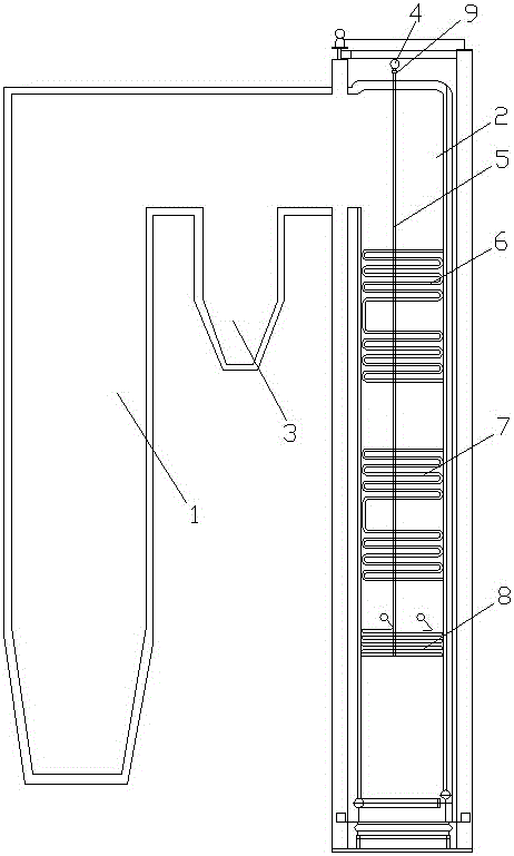
[0044] see figure 1 , a vibrating ash removal circulating fluidized bed boiler, including a furnace 1, a tail flue 2, a separator 3 connecting the furnace 1 and the tail flue 2, and a header 4 located above the tail flue 2, and also includes a penetrating tail The hanging pipe 5 on the top wall of the flue 2, the tail flue 2 is vertically arranged, and the tail flue 2 is provided with a reheater 6, a superheater 7 and an economizer 8 in sequence from top to bottom. The protruding end of the hanging pipe 5 is connected with the header 4, and the protruding end is respectively connected with the reheater 6, the superheater 7 and the economizer 8 in turn, and the header 4 and the tail flue 2 top wall are provided with The pneumatic vibrator 9 is fixed on the hanging pipe 5 through a clamp.

[0045] This embodiment is the most basic implementation mode, with a simple structure, the tail flue is vertically arranged, and a reheater, a superheater and an economizer are arranged ...

Embodiment 2

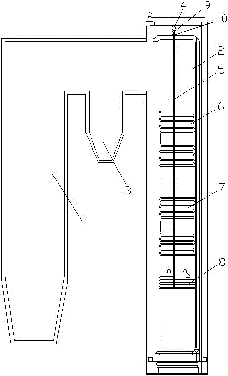
[0047] see figure 2 and image 3 , a vibrating ash removal circulating fluidized bed boiler, including a furnace 1, a tail flue 2, a separator 3 connecting the furnace 1 and the tail flue 2, and a header 4 located above the tail flue 2, and also includes a penetrating tail The hanging pipe 5 on the top wall of the flue 2, the tail flue 2 is vertically arranged, and the tail flue 2 is provided with a reheater 6, a superheater 7 and an economizer 8 in sequence from top to bottom. The protruding end of the hanging pipe 5 is connected with the header 4, and the protruding end is respectively connected with the reheater 6, the superheater 7 and the economizer 8 in turn, and the header 4 and the tail flue 2 top wall are provided with The pneumatic vibrator 9 is fixed on the hanging pipe 5 through a clamp.

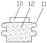
[0048] A corrugated sealing box 10 is provided at the joint between the top wall of the tail flue 2 and the hanging pipe 5, and the corrugated sealing box 10 is composed of a ...

Embodiment 3

[0051] see image 3 and Figure 4 , a vibrating ash removal circulating fluidized bed boiler, including a furnace 1, a tail flue 2, a separator 3 connecting the furnace 1 and the tail flue 2, and a header 4 located above the tail flue 2, and also includes a penetrating tail The hanging pipe 5 on the top wall of the flue 2, the tail flue 2 is vertically arranged, and the tail flue 2 is provided with a reheater 6, a superheater 7 and an economizer 8 in sequence from top to bottom. The protruding end of the hanging pipe 5 is connected with the header 4, and the protruding end is respectively connected with the reheater 6, the superheater 7 and the economizer 8 in turn, and the header 4 and the tail flue 2 top wall are provided with The pneumatic vibrator 9 is fixed on the hanging pipe 5 through a clamp.

[0052] A corrugated sealing box 10 is provided at the joint between the top wall of the tail flue 2 and the hanging pipe 5, and the corrugated sealing box 10 is composed of a ...


PUM


Abstract

The invention discloses a vibration ash removal type circulating fluidized bed boiler. The bed boiler comprises a hearth, a rear smoke channel, a separator and a collection box, wherein the separator connects the hearth with the rear smoke channel, and the collection box is located above the rear smoke channel. The vibration ash removal type circulating fluidized bed boiler is characterized by further comprising a hanging tube penetrating the top wall of the rear smoke channel, the rear smoke channel is arranged vertically, and a reheater, a superheater and a coal economizer are sequentially arranged inside the rear smoke channel from top to bottom; the stretching-out end of the hanging tube is connected with the collection box, and the stretching-in end of the hanging tube is sequentially connected with the reheater, the superheater and the coal economizer; and a pneumatic vibrator is arranged between the collection box and the top wall of the rear smoke channel, and the pneumatic vibrator is fixed to the hanging tube through a clamp. According to the vibration ash removal type circulating fluidized bed boiler, heating surface tube bundles of the reheater, the superheater and the coal economizer are driven by continuous reciprocating vibration of the hanging tube to shake continuously, and ash attached to the heating surface tube bundles falls off and is taken away along with smoke, so that the ash removal efficiency is greatly improved.

Description

technical field [0001] The invention relates to the technical field of circulating fluidized bed boilers, in particular to a circulating fluidized bed boiler which removes ash deposits on a heating surface through vibration in a tail flue of a circulating fluidized bed boiler. Background technique [0002] The structure of the circulating fluidized bed boiler, in addition to the drum, the water wall, the superheater, the reheater, the desuperheater, the economizer, and various connecting pipes and headers, also has a bed material recovery device and a material return device. The slag removal is generally a cold slag machine. Circulating fluidized bed boiler is developed on the basis of bubbling bed boiler fluidized furnace, so some theories and concepts of bubbling bed can be used in circulating fluidized bed boiler. But there is a big difference. The early circulating fluidized bed boiler had a relatively high fluidization velocity, so it was called a fast circulating flu...

Claims


Application Information

Patent Timeline
Patent Type & Authority Applications(China)
IPC IPC(8): F23C10/10F23C10/18F23C10/28F23J3/02
CPCF23C10/10F23C10/18F23C10/28F23J3/02
Inventor 冯静蒋文斌肖雪峰张西平
Owner HMEI THREAD CO LTD OF YINBIN SICHUAN
Why Eureka
Try Eureka